PURE SINE WAVE INVERTER GP-ISW-700/1000/1500/2000/3000/4000 User Manual GP-ISW © 2018 Go Power!® Worldwide Technical Support and Product Information gpelectric.com Go Power! Headquarters 201-710 Redbrick St, Victoria, BC Canada V8T 5J3 Tel: 1.866.247.6527 78158_MAN_ISW_RevD.
3 CFB 4 Congratulations on purchasing your Go Power! GP-ISW Inverter. The unit is a highly reliable DCAC inverter system, designed with advanced power electronic and microprocessor technology offering the following features; • Pure Sine wave output (THD <5%). • Intelligent power management software. • Load and temperature controlled cooling fan. • GP-SWR-A/GP-ISW-R management and control. • Dry contact terminals. • Advance protection features; • Input over/under voltage protection.
1. CONTENTS 2. GENERAL INFORMATION �������������������������������������������������������������������������������������������������4 2.1 CAUTIONS / WARNINGS ���������������������������������������������������������������������������������4 2.2 DISCLAIMERS �����������������������������������������������������������������������������������������������10 2.3 GP-ISW KIT PARTS ��������������������������������������������������������������������������������������� 11 2.3.1 3.
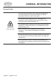
2. GENERAL INFORMATION 2.1 CAUTIONS / WARNINGS This document contains important safety instructions for the products produced by Go Power. Read all instructions and cautionary markings on the product and on any accessories or additional equipment included in the installation. Failure to follow these instructions could result in severe shock or possible electrocution. Use extreme caution at all times to prevent accidents.
GENERAL INFORMATION WARNING! Hazard to Human Life This type of notation indicates that the hazard could be harmful to human life. WARNING! Shock Hazard Danger of shock or electrocution. WARNING! Burn / Fire Hazard Danger of hot surface and/or fire. CAUTION! Hazard to Equipment i IMPORTANT This type of notation indicates that the hazard may cause damage to the equipment.
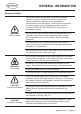
GENERAL INFORMATION Personal Safety Use safe lifting techniques when lifting this equipment as recommended by the Occupational Safety and Health Association (OSHA) or other local codes. Use standard safety equipment when working on this equipment, such as safety glasses, ear protection, steeltoed safety boots, safety hard hats, etc. WARNING! Personal Injury Use standard safety practices when working with electrical equipment. (Remove all jewelry, use insulated tools, wear cotton clothing, etc.
GENERAL INFORMATION Equipment Safety Review the system configuration to identify all possible sources of energy. Ensure ALL sources of power are disconnected before performing any installation or maintenance on this equipment. Confirm that the terminals are de-energized using a validated voltmeter (rated for a minimum 1000 VAC and 1000 VDC) to verify the deenergized condition.
GENERAL INFORMATION Battery Safety Ensure the cables (conductors) are properly sized. Ensure clearance requirements are strictly enforced around the batteries. Ensure the area around the batteries is well ventilated and clean of debris. Never smoke, or allow a spark or flame near, the batteries. WARNING! Explosion, Electrocution, or Fire Hazard Always use insulated tools. Avoid dropping tools onto batteries or other electrical parts. Never charge a frozen battery. Never use old or untested batteries.
Use the battery types recommended by Go Power. Follow the battery manufacturer’s recommendations for installation and maintenance. Insulate batteries as appropriate against freezing temperatures. A discharged battery will freeze more easily than a charged one. i IMPORTANT If a remote or automatic generator control system is used, disable the starting circuit and/or disconnect the generator from its starting battery while performing maintenance to prevent accidental starting.
GENERAL INFORMATION 2.2 DISCLAIMERS IMPORTANT: Please follow installation and wiring instructions exactly as outlined to ensure safety. We recommend installation by an RV/marine technician or professional electrician to ensure adherence to relevant electrical codes.
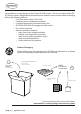
GENERAL INFORMATION 2.3 GP-ISW KIT PARTS Please unpack and make sure all parts shown in the list below are included in the kit. If any parts are missing please contact Carmanah’s customer service team at customerservice@ gpeledtric.com or 1.866.247.6527. 2.3.1 PARTS CHECKLIST ITEM # DESCRIPTION 01 GP-ISW Unit 1 02 Ring lugs 2 03 Phillips Screws 4 04 DC Terminal Covers 2 4 3 2 1 gpelectric.
GENERAL INFORMATION 2.4 GP-ISW FEATURES A B E E C D F A B E E C D F A B E C F E D A Power saving adjustment - This dial is used to adjust the power saving function, it is used to set the input and wake up power thresholds (see page 33). B Function Switch - This dip switch is used to select between different voltages, frequencies and to turn the power saving mode ON and OFF (see page 31).
GENERAL INFORMATION 1 2 4 3 1 4 2 3 4 1 2 3 4 4 1 Remote port - Use this port to connect the optional remote control unit to the Inverter. 2 Remote control green terminal - This terminal may be connected to a form C relay for “FAULT” indication. When “FAULT” occurs, the relay switches. 3 Chassis Ground - Use this connection to ground the exposed chassis of the inverter to the chasis ground.
GENERAL INFORMATION 2.5 UNIT DIMENSIONS AC Output Side AC Output Side B B E E C A A C DC Input Side D ISW-700/1000 DC Input Side D ISW-1500/2000/3000/4000 F F Model A (mm) B (mm) C (mm) D (mm) E (mm) F (mm) GP-ISW700 330 80 132 200 7.0 83 GP-ISW1000 372 69 196 200 7.0 83 GP-ISW1500 421 92 196 248 7.0 83 GP-ISW2000 443 103 196 248 7.0 83 GP-ISW3000 442 103 196 255 7.0 158 GP-ISW4000 462 113 196 255 7.0 158 [page 14] | gpelectric.
GENERAL INFORMATION 2.6 VOLTAGE AND TEMPERATURE PERFORMANCE 175% 200% 1 Sec Power (W) Power (W) 115% 1 Sec 1 Min 100% 10.5V 21V 42V 1 Min 100% 1 Sec Continue 0% 115% 16V 32V 64V 0% 16.5V 33V 66V 10.5V 21V 42V Voltage (V) ISW-700~2000 Power / Voltage Curve 16V 32V 64V 16.
3. INSTALLATION 3.1 TYPICAL SYSTEM OVERVIEW The following diagrams on pages 16-19 show how the GP-ISW-Inverter and GP-ISW-R are typically installed in a mobile RV application. The diagrams show where the remote and Inverter are installed and how the mobile power system can be integrated with a Go Power! RV Solar Kit (sold separately by Go Power, please contact an authorized dealer directly). Solar Panels Refrigerator Vent Cover Inte Vi [page 16] | gpelectric.
INSTALLATION GP-ISW Remote Solar Controller ole ns Co RV ea Ar ernal iew Cable to Battery Bank Cable to GP-ISW Unit Cables to / from Battery Bank Cables From Solar Charge Controller GP-ISW Inverter AC Power OUTPUT - to RV appliances Battery Bank gpelectric.
INSTALLATION Solar Panel Solar Panel AC Loads Refrigerator Vent Cover or Cable Entry Plate Solar Charge Controller Earth Ground (RV Ground) Fuse To Battery Bank To Battery Bank [page 18] | gpelectric.
INSTALLATION ISW Remote Control (Optional) GP-ISW DC Panel ON OFF Battery Disconnect Switch (not required if circuit breaker is used) Fuse or Circuit Breaker Battery Bank gpelectric.
INSTALLATION 3.2 MOUNTING REQUIREMENTS 1. TEMPERATURE Make sure the GP-ISW is installed in a location where the normal air temperature is between -20°C and 40°C. The cooler the better within this range. 2. MOISTURE Do not allow water or other fluids to come into contact with the GP-ISW. Do not expose to rain, snow or water. 3. VENTILATION For optimum Inverter performance the GP-ISW must be installed so the front and rear air vents are not blocked or obstructed in any way.
INSTALLATION HORIZONTAL WALL MOUNT, BASE DOWN HORIZONTAL WALL MOUNT, BASE DOWN HORIZONTAL MOUNT, BASE DOWN HORIZONTAL MOUNT, BASE UP VERTICAL MOUNT, DO NOT MOUNT THE GP-ISW IN THIS CONFIGURATION gpelectric.
INSTALLATION Solar Panel 3.3 DC WIRING ISW Remote Control (Optional) GP-ISW AC Loads DC Panel ON OFF Battery Disconnect Switch (not required if circuit breaker is used) Earth Ground (RV Ground) Fuse or Circuit Breaker Fuse Battery Bank To Battery Bank To Battery Bank The following points must be observed for the DC Wiring. • The DC positive and negative cables connected to the GP-ISW from the battery bank should be linked together with zip ties or electrical tape every 6”.
INSTALLATION 3.3.1 DC WIRING SIZING The distance between the battery bank and the GP-ISW should be as short as possible to achieve maximum efficiency and to reduce fire hazards. The size of the cable should be thick enough to limit the voltage drop to less than 2% when carrying the maximum input current to prevent frequent low-input voltage warnings and shutdown. Only use high quality copper wire. For greater efficiency, the cables should be as short as possible.
INSTALLATION 3.3.2 DC OVERCURRENT PROTECTION AND DC DISCONNECT Batteries are capable of providing very large currents in case of a short circuit, if this occurs with no DC overcurrent protection, it will result in overheating and melting of the cables and possibly serious injury and/or fire. DC overcurrent protection is not included with the GP-ISW Inverters. It must be installed between the Inverter and battery bank for safety reasons and to comply with code regulations.
INSTALLATION To help prevent seizing and corrosion around the terminals the use of an anti-seize lubricant is highly recommended. Apply the antioxidant grease or spray after all the connections are made and tightened. 3.3.5 WIRING THE INVERTER TO THE BATTERIES WARNING: Lethal currents will be present if the positive and negative cables attached to the battery bank touch each other. During the installation and wiring process, ensure the cable ends are insulated or covered to prevent shorting the cables.
INSTALLATION 3.3.6 DC GROUNDING To protect against electrical shock hazards the GP-ISW metal chassis must be connected to the DC grounding system. The DC grounding system is sometimes referred to as the Earth ground or another designated ground. For example on an RV, the metal frame of the RV is designated as the negative DC ground / RV ground. The DC ground wire connection on the GP-ISW is used to connect the exposed chassis of the Inverter to the DC grounding system.
INSTALLATION 3.4.1 AC OUTPUT INTERFACE Socket Type (F) Model GP-ISW700/1000-12/24 GP-ISW1500/2000-12/24 North America (GFCI) GP-ISW3000-12/24 GP-ISW4000-24 Hardwire GP-ISW 3000/4000 AC OUTPUT INTERFACE Terminal (F) AC Terminal Line (L) Neutral (N) Ground Wire Colour Wire AWG Black 200-240 VAC: #10 100-120 VAC: #8 White 200-240 VAC: #10 100-120 VAC: #8 Green / Yellow or Bare Copper #8 to #10 Max Wire Length Up to 16ft Up to 32ft gpelectric.
INSTALLATION 3.4.2 GFCI (GROUND FAULT CIRCUIT INTERRUPTION) OUTLETS Compliance with UL standards requires that Go Power! test and recommend specific GFCIs for use on the AC output of the GP-ISW. GFCIs shall be installed in the AC output wiring system to protect all branch circuits. A GFCI is a device that de–energizes a circuit when a current exceeds a specified value that is less than that required to open the circuit breaker.
4.1 FINAL INSPECTION 1. 2. 3. 4. 5. 4. OPERATION Verify all cables / conduit runs are secured with zip ties or other non-conductive cable clamps to prevent damage from vibration. Ensure all cables that pass through walls, bulkheads or any other openings are protected against abrasion by using strain reliefs and/or grommets. Check all AC, DC and ground connections are securely tightened, and if required covered with suitable anti-seizing grease.
B B E C D E C D F A B B B E C E C D F D 4.4 LED INDICATORS A C OPERATION A A B B C E D C E D F 4.4.1 INPUT VOLTAGE LEVEL LED status DC 12V DC 24V Red < 11.0V < 22.0V Orange 11.0 ~ 11.5V 22.0 ~ 23.0V Green 11.5 ~ 15.0V 23.0 ~ 30.0V Orange 15.0 ~ 15.5V 30.0 ~ 31.0V Red >15.5V >31.0V [page 30] | gpelectric.
OPERATION 4.4.2 INVERTER STATUS TO DISPLAY FAULT CONDITION LED status Status Green Recovery point Normal Red Over Current Protection / Over Load Protection (AC output short-circuit and over load) Red Blink Under Voltage Protection (Input DC voltage under spec) 12.5V @ DC12V system 25V @ DC24V system Red Fast Blink Over Voltage Protection (Input DC voltage over spec) 14.
OPERATION 4.5.1 OUTPUT VOLTAGE SELECTION (S1&S2) Output Voltage S1 S2 100V OFF OFF 110V ON OFF 115V OFF ON 120V ON ON 4.5.2 OUTPUT FREQUENCY SELECTION (S3) Frequency S3 50Hz OFF 60Hz ON 4.6 POWER SAVING SELECTION (S4) Saving Function S4 Power Saving OFF OFF Power Saving ON ON [page 32] | gpelectric.
OPERATION 4.7 SHUTDOWN CONDITIONS Over Voltage (DC) Under Voltage (DC) Shutdown Restart Under Voltage Alarm 12V 16.5V ± 0.3V 14.5V± 0.3V 10.5V ± 0.3V 10.5V ± 0.3V 12.5V± 0.3V 24V 33V ± 0.5V 29V ± 0.5V 21V± 0.5V 21V ± 0.5V 25V ± 0.5V Model Model 12V 24V Shutdown Restart Over Temperature Protection Shutdown Restart 80°C 60°C gpelectric.
5. WARRANTY RETURN PROCEDURE The Go Power! warranty is valid against defects in materials and workmanship for the specific product warranty period.
6. SPECIFICATIONS Electrical Input Characteristics Specification Item GP-ISW700-12 GP-ISW700-24 Voltage 12VDC 24VDC IInput Over Voltage Protection (1) 16.5 ± 0.3VDC 33 ± 0.5VDC Input Under Voltage Protection 10.5 ± 0.3VDC 21 ± 0.5VDC Voltage Range 10.5~16.5VDC 21~33VDC No Load Current ≦1.5A @12VDC ≦0.8A @24VDC Power Saving Mode Output Characteristics Control Protection Environment Safety & EMC <0.1A @12VDC <0.
SPECIFICATIONS Electrical Input Characteristics Specification Item GP-ISW1000-24 Voltage 12VDC 24VDC Input Over Voltage Protection (1) 16.5 ± 0.3VDC 33 ± 0.5VDC Input Under Voltage Protection 10.5 ± 0.3VDC 21 ± 0.5VDC Voltage Range 10.5~16.5 VDC 21~33 VDC No Load Current ≦1.5A @12VDC <0.06A @24VDC Power Saving Mode Output Characteristics Control Protection Environment Safety & EMC ≦0.8A @24VDC <0.
SPECIFICATIONS Electrical Input Characteristics Specification Item GP-ISW1500-24 Voltage 12VDC 24VDC Input Over Voltage Protection (1) 16.5 ± 0.3VDC 33 ± 0.5VDC Input Under Voltage Protection 10.5 ± 0.3VDC 21 ± 0.5VDC Voltage Range 10.5~16.5 VDC 21~33 VDC No Load Current ≦1.8A @12VDC <0.05A @24VDC Power Saving Mode Output Characteristics Control Protection Environment Safety & EMC ≦1.0A @24VDC <0.
SPECIFICATIONS Electrical Input Characteristics Specification Item GP-ISW2000-12 GP-ISW2000-24 Voltage 12VDC 24VDC Input Over Voltage Protection (1) 16.5 ± 0.3VDC 33 ± 0.5VDC Input Under Voltage Protection 10.5 ± 0.3VDC 21 ± 0.5VDC Voltage Range 10.5~16.5 VDC 21~33 VDC No Load Current ≦1.8A @12VDC <0.05A @24VDC Power Saving Mode Output Characteristics Signal and Control Protection Safety & EMC Model No. ≦1.0A @24VDC <0.
SPECIFICATIONS Electrical Input Characteristics Specification Item GP-ISW3000-12 GP-ISW3000-24 Voltage 12VDC 24VDC Input Over Voltage Protection (1) 16.5 ± 0.3VDC 33 ± 0.5VDC Input Under Voltage Protection 10.5 ± 0.3VDC 21 ± 0.5VDC Voltage Range 10.5~16.5 VDC 21~33 VDC No Load Current ≦3.8A @12VDC ≦2.0A @24VDC Power Saving Mode Output Characteristics Signal and Control Protection Safety & EMC Model No. <0.4A @12VDC <0.
SPECIFICATIONS Electrical Input Characteristics Output Characteristics Signal and Control Protection Safety & EMC Specification Item Model No. GP-ISW4000-24 Voltage 24VDC Input Over Voltage Protection (1) 33 ± 0.5VDC Input Under Voltage Protection 21 ± 0.5VDC Voltage Range 21~33 VDC No Load Current Power Saving Mode ≦2.0A @24VDC Continuous Output Power 4000 VA (± 3%) Maximum Output Power (1Min) > 4000 VA~4600 VA (100%~115%) Surge Power (1Sec) < 8000 VA Frequency 50 / 60 Hz ± 0.
7. END OF LIFE - RECYCLING Product E.O.L (End of life) Information This product required the extraction and use of natural resources. It may contain substances that could be harmful to the environment or human health if improperly handled at the product’s end of life.
© 2018 Go Power!® Worldwide Technical Support and Product Information gpelectric.com Go Power! Headquarters 201-710 Redbrick St, Victoria, BC Canada V8T 5J3 Tel: 1.866.247.6527 78158_MAN_ISW_RevD.