GP-PWM-10-FM (with LiFePO4) ________________________________________________________________________ GP-PWM-10-FM User Manual © 2019 Go Power!
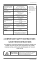
GP-PWM-10-FM Contents 1.0 Installation Overview 3 1.1 Introduction 3 1.2 System Voltage and Current 3 1.3 Battery Type 3 1.4 Low Voltage Disconnect Function (USB Port) 4 1.5 Regulatory Information 4 1.6 Specifications 4 2.0 IMPORTANT SAFETY INSTRUCTIONS 5 3.0 Tools and Materials Needed 8 4.0 Choosing a Location 8 5.0 Installation Instructions 9 6.0 Wiring Diagram 12 7.0 Operating Instructions 13 7.1 Power Up 13 7.2 Setting the Battery Charging Profile 13 7.
GP-PWM-10-FM 1.0 Installation Overview 1.1 Introduction A Solar Controller (or Charge Controller / Regulator) is an essential component of your photovoltaic solar system. The Controller maintains the life of the battery by protecting it from overcharging. When your battery has reached a 100% state of charge, the Controller prevents overcharging by limiting the current flowing into the batteries from your solar array.
GP-PWM-10-FM 1.4 Low Voltage Disconnect Function (USB Port) To protect the battery against over-discharge this function automatically switches off the USB output port when battery voltage is lower than 11.0 VDC. As soon as the battery reaches a voltage of 12.8 VDC the USB output port is switched on again. 1.5 Regulatory Information 1.6 Specifications Description Model Nominal System Voltage Range of Battery Input Value GP-PWM-10-FM 12 VDC 12.5 ADC 9 – 14.
GP-PWM-10-FM Bulk/Absorption Voltage 14.1/14.4/14.4 VDC Compensated (Sealed/GEL, AGM/LFP, (25°C / 77°F), 30min / Day • RoHS Compliant, Flooded) or 2hr if battery voltage < 12.3 VDC Float Voltage 13.7V (25°C / 77°F), 14.0V (LFP) Equalization Voltage 14.9V (25°C / 77°F), Environmentally Safe • Accepts up to 160 Watts of Solar at 12 Volts 2h / 28 Days or if battery voltage < 12.1 VDC Temperature Compensation - 24mV/ºC / -13mV/ºF USB charger 5V, 1500mA Low Voltage Disconnect (USB) 11.
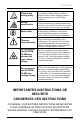
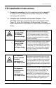
GP-PWM-10-FM Battery and wiring safety Wiring connections Work safely Observe correct polarity Do not exceed the GP-PWM10-FM Amp current and max voltage ratings Do not exceed the GP-PWM10-FM max voltage ratings Observe all safety precautions of the battery manufacturer when handling or working around batteries. When charging, batteries produce hydrogen gas, which is highly explosive. Ensure all connections are tight and secure. Loose connections may generate sparks and heat.
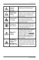
GP-PWM-10-FM Débranchez toutes les sources d’énergie Sécurité de la batterie et du câblage Branchements de câblage Travaillez en toute sécurité Respectez la polarité correcte Ne dépassez pas le courant nominal maximum du GP-PWM-10-FM L’électricité peut être très dangereuse. L’installation ne doit être effectuée que par un électricien agréé ou du personnel qualifié.
GP-PWM-10-FM Ne dépassez pas la tension nominale maximum du GP-PWM-10-FM La tension maximum des panneaux est la somme de la tension à vide du module PV des modules connectés en série, multipliée par 1,25 (ou par une valeur de l’article 690.7 du Code National Électrique fournie dans le tableau 690.7 A). La tension qui en résulte ne doit pas excéder 35 V. Si votre système solaire dépasse cette valeur, veuillez contacter votre revendeur pour obtenir un régulateur plus approprié. 3.
GP-PWM-10-FM 5.0 Installation Instructions 1. Prepare for mounting. Use the template provided on page 27 to mark the four mounting holes and the cutting line for flush mounting your controller. 2. Complete the installation of the solar modules. If this GP-PWM-10-FM was purchased as part of a Go Power! Solar Power Kit, follow the Installation Guide provided. Otherwise, follow manufacturer’s instructions for solar module mounting and wiring.
GP-PWM-10-FM 3. Select wire type and gauge. If this GP-PWM-10-FM was purchased as part of a Go Power! Solar Power Kit, appropriate wire type, gauge, and length is provided. Please continue to Section 6, “Operating Instructions.” If the GP-PWM-10-FM was purchased separately, follow the instructions included here. Wire type is recommended to be a stranded copper UV-resistant wire. Wire fatigue and the likelihood of a loose connection are greatly reduced in stranded wire compared to solid wire.
GP-PWM-10-FM 5. Torque all terminal screws per the following: Stranded Copper 90°C Wire Wire Size AWG 14 12 10 Rated Torque (in-lbs) 20 20 20 With battery power attached, the controller should power up and display information. Connect the solar wiring to the controller and remove the opaque material from the solar array. The negative solar array and battery wiring must be connected directly to the controller for proper operation.
GP-PWM-10-FM 6.0 Wiring Diagram IMPORTANT: This diagram is valid only for version 1.5 and newer. Version 1.4 and older have different terminal locations. The GP-PWM-10-FM Maximum 12.5A rating is based on a 10 amp total maximum short circuit current rating (Isc) from the parallel solar modules nameplate ratings. The National Electric Code specifies the PV equipment/system rating to be 125% of the maximum Isc from the PV module nameplate ratings (1.25 times 10 = 12.5A).
GP-PWM-10-FM 7.0 Operating Instructions 7.1 Power Up When the GP-PWM-10-FM is connected to the battery, the controller will go into Power Up mode. Icons Displayed: All segments of the numerical display; backlight blinks. Depending on the battery voltage when the GP-PWM-10-FM Power Up occurs, the controller may do a Boost Charge or quickly go into Float Charge. The Charging Profile selected will commence the following day after a Power Up (refer to the Charging Profile Chart on page 11 for more details).
GP-PWM-10-FM 7.3 Battery Charging Profile Chart Battery Type SEALED /GEL Float Charge @ 25°C: Equalization Charge @ 25°C: Applied for 2 hours every 28 days and if the battery voltage drops below 12.1 volts. FLOODED LFP 13.7V (+/- 0.1V) Bulk/Absorption Charge @ 25°C: Set to 30 minutes every morning. Applied for 2 hours if the battery voltage drops below 12.3 volts. AGM N/A 14.1V (+/- 0.1V) 14.4V (+/0.1V) 14.4V (+/- 0.1V) N/A N/A N/A 14.9V (+/-0.
GP-PWM-10-FM Push the B Button to show the battery voltage. Icons Displayed: Battery SOC, Volt Symbol (V) Push the B Button to show the PV charging current. Icons Displayed: Ampere Symbol (A), Battery SOC Push the B Button to show the battery state of charge (shown as a percentage).
GP-PWM-10-FM A value of 100% will only be displayed after a Boost or Equalize charge completes. Push the B Button to show the number of amp hours charged since the last reset. Icons Displayed: Amp hours charged, Amp hour symbol (Ah) or kiloamp hour symbol (kAh) 7.5 Resetting the ampere hours charged To reset the count of ampere hours charged, toggle to the ampere hours charged. Press and hold the A Button for 6 seconds to reset the counter to zero.
GP-PWM-10-FM 7.6 Errors Over Voltage If the GP-PWM10-FM experiences a battery over voltage (15.5V), the controller will stop operating, and the display will begin to flash with all icons. The controller will resume operating when the error is cleared. Icons Displayed: All symbols Low Voltage If the battery voltage reaches 11 volts, the battery SOC symbol will show the text “LOW” beneath it.
GP-PWM-10-FM 8.0 Display Symbols Symbol Indicator For: Day Time: PV Charge Current Night Time Battery Voltage Battery State of Charge SEALED AGM FLOODED Sealed/Gel AGM/LFP Flooded Other Symbols USB charger on (When charger is off, no symbol will show) Battery voltage is lower than LOW 11.0 VDC Whole display will start to blink Battery voltage > 15.5 VDC Battery State of Charge Symbol Battery Voltage Shows only after full Boost or Equalization Cycle >= 12.6 VDC >= 11.8 -12.6 VDC > 11.0 -11.
GP-PWM-10-FM <= 11.0 VDC 𝑆𝑆𝑆𝑆𝑆𝑆 = 9.0 100% Shows only after full Boost or Equalization Cycle 90% >= 12.8 VDC 𝑏𝑏𝑏𝑏𝑏𝑏𝑏𝑏𝑏𝑏𝑏𝑏𝑏𝑏 𝑣𝑣𝑣𝑣𝑣𝑣𝑣𝑣𝑣𝑣𝑣𝑣𝑣𝑣 − 11.0𝑉𝑉 ∗ 90% 1.8𝑉𝑉 0% <12.8 VDC and > 11.0 VDC <= 11.0 VDC USB Charging The GP-PWM-10-FM offers a standard USB connector for delivering 5.0 VDC to small mobile appliances such as cell phones, tablets or small music players. This charging port is capable of supplying up to 1500 mA of current. Remove the rubber cover of the USB terminal to access the terminal.
GP-PWM-10-FM It seems like my flooded batteries are losing water over time. Flooded batteries may need to have distilled water added periodically to replace fluid loss during charging. Excessive water loss during a short period of time indicates the possibility of overcharging or aging batteries. When charging, my flooded batteries are emitting gas. During charging, hydrogen gas is generated within the battery. The gas bubbles stir the battery acid, allowing it to receive a fuller state of charge.
GP-PWM-10-FM Why does the battery SOC% never reach 100%? A 100% value will only appear after a 2 hour Boost or Equalize charge has completed. The charge voltage must be maintained for an extended period of time to replenish the energy in the battery bank back to its rated capacity. If the charge voltage cannot be maintained continuously, then the actual time it takes to complete Boost or Equalize charging may take much longer than 2 hours, even more than 1 day.
GP-PWM-10-FM 2. If there is no voltage reading at the controller battery terminals, the problem is in the wiring between the battery and the controller. If the battery voltage is lower than 6 volts, the controller will not function. 3. For the solar array, repeat steps 1 and 2 substituting all battery terminals with solar array terminals. Remedy: Check all connections from the controller to the battery including checking for correct wire polarity. Check that all connections are clean, tight, and secure.
GP-PWM-10-FM 2. If there is a voltage discrepancy of more than 0.5 VDC, there is an excessive voltage drop. Remedy: Check all connections from the controller to the battery including checking for correct wire polarity. Check that all connections are clean, tight, and secure. Shorten the distance from the controller to battery or obtain larger gauge wire. It is also possible to double up the existing gauge wire (i.e. two wire runs) to simulate a larger gauge wire.
GP-PWM-10-FM Possible Cause: Current is being limited below 1 Amp as per normal operation or poor connection between solar array and controller. How to tell: 1. The State of Charge (SOC) screen is close to 100% and the Sun and Battery icon are present with an arrow between. 2. With the solar array in sunlight, check the voltage at the controller solar array terminals with a voltmeter. 3.
GP-PWM-10-FM (3) Modules look dirty, overhead object is shading modules or it is an overcast day in which a shadow cannot be cast. Avoid any shading no matter how small. An object as small as a broomstick held across the solar module may cause the power output to be reduced. Overcast days may also decrease the power output of the module. (4) Disconnect one or both array wires from the controller. Take a voltage reading between the positive and negative array wire.
GP-PWM-10-FM 12.0 Limited Warranty Go Power! warrants the GP-PWM-10-FM for a period of five (5) years from the date of shipment from its factory. This warranty is valid against defects in materials and workmanship for the five (5) year warranty period.
GP-PWM-10-FM 27 © 2018 Go Power!
GP-PWM-10-FM © 2019 GO POWER!® MOBI_MAN_GP-PWM-10-FM_RevD gpelectric.