PORTABLE SOLAR KITS User Manual GP-PSK-80 GP-PSK-120 © 2016 Go Power! By Carmanah Technologies Worldwide Technical Support and Product Information gpelectric.com ® Carmanah Technologies Corporate Headquarters 250 Bay St, Victoria, BC Canada V9A 3K5 Tel: 1.866.247.
® 1. CONTENTS 2. GENERAL INFORMATION ����������������������������������������������������������������������������������������� 4 2.1 WARNINGS ���������������������������������������������������������������������������������������������������� 4 3. FEATURES AND ACCESSORIES ������������������������������������������������������������������������������ 5 3.1 ADDITIONAL ACCESSORIES SOLD SEPARATLEY ������������������������������������� 5 4.
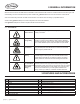
® 2.GENERAL INFORMATION Welcome to the Go Power! Portable Solar Kit Installation Guide. Please read all instructions contained within this manual to gain a full understanding of how to install and use this product. Please visit gpelectric.com for the most current version of this manual. Visit our Go Power! By Carmanah YouTube channel to watch a two minute video on setting up a portable solar kit. Veuillez visiter gpelectric.com pour la version française de ce manuel de l’utilisateur Visite gpelectric.
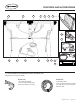
® 12 FEATURES AND ACCESSORIES 5 6 10 3 2 11 14 15 13 9 8 7 4 1 16 17 3.1 ADDITIONAL ACCESSORIES SOLD SEPARATELY Visit gpelectric.com for product details. GP-PSK-7PIN 7 Pin Trailer Plug Adapter - Use your existing trailer plug to access your battery for charging GP-PSK-X30 30’ Extension Cable - Park your RV in the shade and place your solar panel in the sun using this extension cable. gpelectric.
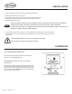
® 4.INSTALLATION 1. Locate a sunlit area, free from overhanging branches or obstructions. 2. Remove solar panel kit from carrying case. 3. Unclip the two latches on the side of the unit and fold the two panels outward. Extend the two support legs to their maximum length and lock in position. 4. Place solar panel facing the sun. Note Avoid any shading no matter how small. An object as small as a broomstick held across the solar module may cause the power output to be reduced.
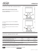
® OPERATION 5.2 SETTING THE BATTERY CHARGING PROFILE To select the battery charging profile, press and hold the B Button. This will cause the current battery type to flash. Then, press the B Button to toggle through the profile options: Sealed/Gel, AGM or Flooded. To confirm the battery profile, press and hold the A Button for 3 seconds. Non-volatile memory: Any settings made on the GP-PWM-10 will be saved even when the power has been disconnected from the controller.
® 5.4 MAXIMUM POWER BOOST TECHNOLOGY™ Maximum Power Boost Technology™ (MPBT) allows you to override the normal charging algorithm of the solar controller. MPBT is designed to be used before the end of the day, if you know you will require many loads through the night. This feature can also be used when you have just installed the solar controller, to put batteries on a boost charge up to 14.4V (Flooded and AGM) or 14.1V (Sealed/Gel) right away. To activate, hold the B Button for 3 seconds.
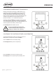
® OPERATION Push the B Button to show the battery state of charge (shown as a percentage). Icons Displayed: Battery SOC, Percent Symbol (%) 5.6 ERRORS Over Voltage If the GP-PWM-10 experiences a battery over voltage (15.5V), the controller will stop operating and the display will begin to flash with all icons. The controller will resume operating when the error is cleared.
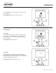
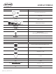
® 6.DISPLAY SYMBOLS SYMBOL INDICATOR FOR: Day Time: PV Charge Current Night Time Battery Voltage Battery State of Charge SEALED Sealed/Gel Battery Type Selected AGM AGM Battery Type Selected FLOODED Flooded Battery Type Selected USB Charger On (when charger is off, no symbol will show) BOOST Controller tries to keep battery at Boost Voltage or higher LOW Battery Voltage is lower than 11.0V Whole display will start to blink Battery Voltage > 15.
® 7.USB CHARGING The GP-PWM-10 controller offers a standard USB connector for delivering 5V to small mobile appliances such as cell phones, tablets and small music players. This charging port is capable of supplying up to 800 mA of current. Icons Displayed: USB symbol (appears only when port is active) The controller disables the USB charger automatically if the battery voltage drops below 11.0V. If there is enough current from the PV panel/array available to charge the Battery to above 12.
® SPECIFICATIONS 8.2 SOLAR CONTROLLER SPECIFICATIONS DESCRIPTION VALUE Nominal System Voltage 12V Max. Solar Array Current 10A Battery Voltage Range 6 - 15.5V Max. Solar Voltage 28V Operating Consumption (display backlight on) 15mA Operating Consumption (display backlight off) 6mA Sealed/ Gel 14.1V Bulk/Absorption Voltage (77°F / 25°C), 1 - 2h / Day AGM 14.4V Float Voltage (77°F / 25°C) 13.7V Equalize Charging Voltage (77°F / 25°C) 2h / 28 Day or V < 12.1 14.
® FREQUENTLY ASKED QUESTIONS Q3. My voltmeter shows a different reading than the GP-PWM-10 display A. The meter value on the GP-PWM-10 display is an approximate reading intended for indication purposes only. There is an approximate 0.1 volt inherent error present that may be accentuated when compared with readings from another voltmeter. There may be a slight difference between the battery voltage displayed on the GP-PWM-10 display and the battery voltage measured at the battery terminals.
® Topic TROUBLESHOOTING Issue Possible Cause How to Tell Remedy Current reading shows 0A at daytime, with clear sunny skies Current is being limited below 1A as per normal operation or poor connection between solar array and controller. 1. The State of Charge (SOC) screen is close to 100% and the Sun and Battery icon are present with an arrow between. Hold down the MAX BOOST Button for approximately 3 seconds to activate Maximum Power Boost.
® 11.LIMITED WARRANTY Go Power! warrants the solar panel of the Portable Solar Kit for 25 years, 1 year for the cable and components and 5 years for the solar controller. This warranty is valid against defects in materials and workmanship.