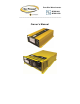
Pure Sine Wave Inverter GPSW-600 GPSW-1500 ________________________________________________ Owner’s Manual
GPSW-600/1500 ___________________________________________________________ Table of Contents Introduction 2 Specifications 3 Name and Main Function 5 Installation 9 Operation 11 Operating Limits 12 Troubleshooting 13 Maintenance 14 Disclaimer of Liability and Warranty 15 Configuring your GPSW-600/1500 18 1. Introduction The Go Power! Sine Wave series models are used in a wide range of applications including remote homes, RVs, sailboats and powerboats.
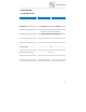
GPSW-600/1500 ___________________________________________________________ 2. Specifications 2.1 1500 W Inverter SPECIFICATIONS GPSW-1500 (12V) Continuous Output Power Surge Rating 1500 W 2000 W Output Waveform Output Voltage ± 5% Input Voltage Efficiency No Load Current Draw / Powersave Protection Low Battery Alarm ± 2% Low Battery Shut-Down ± 2% Operating Temperature Range Storage Temperature Range Cooling GPSW-1500 (24V) Pure Sine Wave <3% THD 115 VAC RMS 11 – 16.0 VDC 21.0-30.0 85-90% 1.0 A / 0.
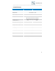
GPSW-600/1500 ___________________________________________________________ 2.2 600 W Inverter SPECIFICATIONS GPSW-600 (12V) Continuous Output Power Surge Rating Output Waveform Output Voltage ± 5% Input Voltage Efficiency No Load Current Draw / Powersave Protection Low Battery Alarm ± 2% Low Battery Shut-Down ± 2% Operating Temperature Range Storage Temperature Range Cooling GPSW-600 (24V) 600 W 860 W Pure Sine Wave <3% THD 115 VAC RMS 10.5– 15 VDC 21.0-30.0 85-92 % 0.90 A 0.
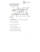
GPSW-600/1500 ___________________________________________________________ 3.0 Name and Main Function 3.1 Front View GPSW-1500 a) ON / OFF switch: Power ON/OFF switch, leave in the OFF position during installation. b) OVP: over voltage protection. c) UVP: under voltage protection d) OTP: over temperature protection. e) OLP: over load protection. f) BATT. VOLTS: display battery voltage. g) LOAD WATTS: display AC load watts.
GPSW-600/1500 ___________________________________________________________ 3.2 Rear View GPSW-1500 Warning! Operation of the inverter without a proper ground connection may result in an electrical safety hazard. a) Ventilation ports: Do not obstruct, allow at least 1 inch for air flow. b) Battery terminals: Connect to 12V / 24V battery or other 12V / 24V power source. [+] is positive [ - ] is negative. Reverse polarity connection will blow the internal fuse and may damage inverter permanently.
GPSW-600/1500 ___________________________________________________________ 3.3 Front View GPSW-600 a) ON / OFF switch: Power ON/OFF switch, leave in the OFF position during installation. b) Ventilation ports: Do not obstruct, allow at least 1 inch for air flow. c) Load Level: Display AC load watts, green indicates normal operation and red indicates high load levels. d) Fault e) Frequency f) Input Level: Display input voltage, green indicates normal operation and red indicates low battery level.
GPSW-600/1500 ___________________________________________________________ 3.4 Rear View GPSW-600 Warning! Operation of the inverter without a proper ground connection may result in an electrical safety hazard. a) Ventilation port: Do not obstruct, allow at least 1 inch for air flow b) Battery terminals: Connect to 12V battery or other 12V power source. [+] is positive [-] is negative. Reverse polarity connection will blow the internal fuse and may damage inverter permanently.
GPSW-600/1500 ___________________________________________________________ 4.0 Installation 4.1 Where to install The power inverter should be installed in a location that meets the following requirements: a) Dry - Do not allow water to drip or splash on the inverter. b) Cool - Ambient air temperature should be between 0°C and 40°C (the cooler the better). c) Ventilated - Allow at least two inches of clearance around the inverter for air flow.
GPSW-600/1500 ___________________________________________________________ 6. Connect the cable from the positive terminal of inverter to the positive terminal of the battery. Make a secure connection. 7. Set the power switch to the ON position. Check the meters and indicators on the front panel of the inverter. The voltage indicator should indicate 12 to 14 volts depending on the voltage of the power source. If it is does not, check your battery bank and the connections to the inverter. 8.
GPSW-600/1500 ___________________________________________________________ electrical code requirements that separately derived AC sources (such as inverters and generators) have their neutral tied to ground in the same way that the neutral conductor from the utility line is tied to ground at AC breaker panel. Caution! The negative DC input of the power inverter is connected to the chassis. Do not install the power inverter in a positive ground DC system.
GPSW-600/1500 ___________________________________________________________ 5.4 Resetting Faults Any of the inverters protection faults can be re-set by turning the inverter off for five seconds and then turning the inverter on again. The GPSW1500 can also reset any of its protection faults using the optional remote on/off switch to turn the inverter off and then on again. 5.
GPSW-600/1500 ___________________________________________________________ When determining whether a microwave oven can be operated by the 1500 W inverter, remember that the power commonly advertised for microwave ovens is the cooking power (the power delivered to the food) not the power actually consumed by the microwave oven. The microwave oven will consume 40% to 100% more than its advertised cooking power. Check the rating sticker on the back of the oven to determine its actual power draw.
GPSW-600/1500 ___________________________________________________________ • Make sure that the antenna feeding your television provides an adequate ("snow free") signal and that you are using good quality cable between the antenna and the TV. • Move the television as far away from the power inverter as possible. • Keep the cables between the battery and the power inverter as short as possible and twist them together with about 2 to 3 twists per foot. This minimizes radiated interference from the cables.
GPSW-600/1500 ___________________________________________________________ 9.0 Disclaimer of Liability & Warranty Go Power!TM provides the following limited 2 year warranty (“Warranty”) coverage as applicable to the purchaser (“Purchaser”) of the Go Power!TM branded product TM (“Product”) directly from Go Power! The following constitutes the terms and conditions of that limited warranty. 9.1.
GPSW-600/1500 ___________________________________________________________ Failure due to fire, water, neglect, improper installation, generalized corrosion, biological infestations, or input voltages that create operating TM conditions beyond the maximum or minimum listed in the Go Power! specifications including lightning strikes.
GPSW-600/1500 ___________________________________________________________ Power!TM Products. TM Go Power! 's liability on any claim, whether in warranty, contract, negligence, or any other legal theory, for loss, damage or injury arising TM directly or indirectly from or in relation to the use of the Go Power! TM Product shall in no event exceed the purchase price of the Go Power! Product which gave rise to the claim.
GPSW-600/1500 ___________________________________________________________ 9.2.3 Units bought directly from Go Power! The Purchaser will return the product, freight prepaid, to Go Power!TM You must obtain a Return Material Authorization (RMA) number from Go Power!TM before returning a product. The RMA number MUST be clearly indicated on the outside of the box. Items received without an RMA number will be refused. 9.2.
GPSW-600/1500 ___________________________________________________________ 10.2 Configuring the GPSW 600 Switches are located on the front panel.
GPSW-600/1500 ___________________________________________________________ © 2011 GO POWER!™ By Carmanah Technologies www.gpelectric.