
Manual


GPSW-600/1500
___________________________________________________________
10
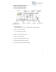
6. Connect the cable from the positive terminal of inverter to the positive terminal
of the battery. Make a secure connection.
7. Set the power switch to the ON position. Check the meters and indicators on
the front panel of the inverter. The voltage indicator should indicate 12 to 14 volts
depending on the voltage of the power source. If it is does not, check your
battery bank and the connections to the inverter.
8. Set the power inverter switch to the OFF position. The indicator lights may
blink and the internal alarm may sound momentarily. This is normal. Plug the test
load into the AC receptacle on the front panel of the inverter. Leave the test load
switch OFF.
9. Set the power inverter switch to the ON position and turn the test load on; the
inverter should supply power to the load. If you plan to measure the output
voltage of the inverter, a true r.m.s. meter must be used for accurate readings.
10. Ensure battery interconnect cables are a minimum of #4 gauge wire and a
maximum of 12” in length.
Caution! A reverse polarity connection will blow a fuse in the inverter
and may permanently damage the inverter. Damage caused by reverse
polarity connection is not covered by our warranty.
Warning!
You may observe a spark when you make this connection since current
may flow to charge capacitors in the power inverter. Do not make this
connection in the presence of flammable fumes, as explosion or fire
may result.
4.3 Cables
DC to AC inverters require high amperage / low voltage DC power to low
amperage / high voltage AC power. To operate properly connect inverter DC
input terminals direct to battery with appropriate Go Power! Install kit.
4.4 Grounding
The power inverter has a lug on the rear panel [chassis ground]. This is to
connect the chassis of the power inverter to the ground. The ground terminals in
the AC outlets on the front panel of the inverter are also connected to the ground
lug.
The chassis ground lug must be connected to a grounding point, which will vary
depending on where the power inverter is installed. In a vehicle, connect the
chassis ground to the chassis of the vehicle. In a boat, connect to the boat's
grounding systems. In a fixed location, connect the chassis ground lug to earth.
The neutral (common) conductor of the power inverter AC output circuit is
connected to the chassis ground. Therefore, when the chassis is connected to
ground, the neutral conductor will also be grounded. This conforms to national