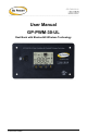
GP-PWM-30-UL ________________________________________________________________________ User Manual GP-PWM-30-UL Dual Bank with Bluetooth® Wireless Technology © 2019 Go Power!
GP-PWM-30-UL _______________________________________________________________________ Contents 1.0 Installation Overview 4 1.1 Introduction 4 1.2 System Voltage and Current 4 1.3 Battery Type 4 1.4 Low Voltage Disconnect Function (USB Port, Inverter Remote Signal) 4 1.5 Bluetooth® Wireless Technology 5 1.6 Regulatory Information 5 1.7 Specifications 5 2.0 IMPORTANT SAFETY INSTRUCTIONS 7 3.0 Tools and Materials Needed 9 4.0 Choosing a Location 9 5.0 Choosing a Battery 9 6.
GP-PWM-30-UL _______________________________________________________________________ 9.0 Display Symbols 22 10.0 Inverter Control (on/off) 24 11.0 USB Charging 25 12.0 Bluetooth® Wireless Technology 26 12.1 Pairing 26 12.2 App Settings 28 12.3 General Info 28 13.0 Frequently Asked Questions (FAQs) 29 14.0 Troubleshooting Problems 31 14.1 Problems with the Display 31 14.2 Problems with Voltage 32 14.3 Problems with Current 32 15.0 16.0 Limited Warranty 35 15.
GP-PWM-30-UL _______________________________________________________________________ 1.0 1.1 Installation Overview Introduction A Solar Controller (or Charge Controller / Regulator) is an essential component of your photovoltaic solar system. The Controller maintains the life of the battery by protecting it from overcharging. When your battery has reached a 100% state of charge, the Controller prevents overcharging by limiting the current flowing into the batteries from your solar array.
GP-PWM-30-UL _______________________________________________________________________ compatible inverter is connected and set to remote mode, the controller will also switch off the inverter. This will occur with a delay of 2 to 3 minutes. As soon as Battery 1 reaches a voltage of 12.2 VDC (for LFP) or 12.8 VDC (for SEALED, AGM, or FLOODED) the USB output port is switched on again. If a compatible inverter is connected and in remote mode, it will also be switched on again. 1.
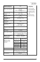
GP-PWM-30-UL _______________________________________________________________________ Operating Consumption (Display backlight off) Battery Types Supported Bulk/Absorption Voltage (Sealed/Gel, AGM, Flooded) 6mA • Temperature Compensated Vented and Sealed (GEL, AGM etc.) Lead Acid Lithium Iron Phosphate (LFP or LiFePO4) 14.1/14.4/14.4V (25°C / 77°F), 30min / Day or 2hr if battery voltage < 12.3V Absorption Voltage (LiFePO4) 14.4V 30min / day Float Voltage (Sealed/Gel, AGM, Flooded) 13.
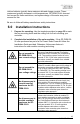
GP-PWM-30-UL _______________________________________________________________________ 2.0 IMPORTANT SAFETY INSTRUCTIONS SAVE THESE INSTRUCTIONS THIS MANUAL CONTAINS IMPORTANT INSTRUCTIONS FOR MODEL GP-PWM-30-UL THAT SHOULD BE FOLLOWED DURING INSTALLATION AND MAINTENANCE OF THE CHARGE CONTROLLER.
GP-PWM-30-UL _______________________________________________________________________ IMPORTANTES INSTRUCTIONS DE SECURITE CONSERVEZ CES INSTRUCTIONS CE MANUAL CONTIENT DES INSTRUCTIONS IMPORTANTES POUR LE MODÈLE GP-PWM-30-UL QUI DOIVENT ÊTRE SUIVIES PENDANT L’INSTALLATION ET L’ENTRETIEN DU GP-PWM-30-UL.
GP-PWM-30-UL _______________________________________________________________________ La tension maximum des panneaux est la somme de la tension à vide du module PV des Ne dépassez pas modules connectés en série, multipliée par 1,25 la tension (ou par une valeur de l’article 690.7 du Code National Électrique fournie dans le tableau 690.7 nominale A). La tension qui en résulte ne doit pas excéder maximum du GP35 V.
GP-PWM-30-UL _______________________________________________________________________ Lithium batteries typically have maximum allowed charge currents. These maximums typically decrease in cold temperatures. GP-PWM-30-UL does not limit current for these restrictions, and system design of the solar array must account for this. Be sure to follow all battery manufacturer safety instructions. 6.0 Installation Instructions 1. Prepare for mounting.
GP-PWM-30-UL _______________________________________________________________________ 3. Select wire type and gauge. If this GP-PWM-30-UL was purchased as part of a Go Power! Solar Power Kit, appropriate wire type, gauge and length is provided. Please continue to Section 8, “Operating Instructions.” If the GP-PWM-30-UL was purchased separately, follow the instructions included here. Wire type is recommended to be a stranded copper UV resistant wire.
GP-PWM-30-UL _______________________________________________________________________ Stranded Copper 90°C Wire Wire Size AWG 10 8 6 4 Rated Torque (in-lbs) 20 25 35 35 With battery power attached, the controller should power up and display information. Connect the solar wiring to the controller and remove the opaque material from the solar array. The negative solar array and battery wiring must be connected directly to the controller for proper operation.
GP-PWM-30-UL _______________________________________________________________________ 7.1 Charging Only One Battery Use the following wiring diagram if you are using the GP-PWM-30-UL to charge only one battery. Connect your battery to the battery 1 terminals on the solar controller. The fuse or breaker used should be no larger than 50 amps The controller will not work unless there is a battery connected to the Battery 1 terminals.
GP-PWM-30-UL _______________________________________________________________________ The fuses or breakers used should be no larger than 50 amps. WARNING: When the photovoltaic (solar) array is exposed to light, it supplies a dc voltage to this equipment AVERTISSEMENT : Lorsque le panneau photovoltaïque (solaire) est exposé à la lumière, il fournit une tension cc à cet équipement. 8.0 8.
GP-PWM-30-UL _______________________________________________________________________ 8.2 Setting the Battery Type and Charging Profile GP-PWM-30-UL Solar Controller with Bluetooth® Wireless Technology GP-PWM-30-UL Solar Controller GP-PWM-30-UL Solar Controller with Bluetooth® Wireless Technology GP-PWM-30-UL SOLAR CONTROLLER GP-PWM-30-UL Solar Controller with Bluetooth® Wireless Technology Setting Battery 1 To set the battery type for battery bank 1, hold the B Button for 3 seconds.
GP-PWM-30-UL _______________________________________________________________________ GP-PWM-30-UL Solar Controller with Bluetooth® Wireless Technology GP-PWM-30-UL SOLAR CONTROLLER To select the charging profile of battery bank 2, press the B Button to toggle through the profile options: Sealed/Gel, AGM, Flooded, or LFP. To confirm the battery profile, press and hold the A Button for 3 seconds.
GP-PWM-30-UL _______________________________________________________________________ SEALED Battery Type Float Charge at 25°C: AGM FLOODED 13.7 VDC LFP N/A Bulk/Absorption Charge at 25°C: Set to 30 minutes every morning. 14.1 VDC 14.4 VDC 14.4 VDC N/A Equalization Charge at 25°C: Applied for 2 hours every 28 days and if the battery voltage drops below 12.1 volts. N/A N/A 14.9 VDC N/A Absorption Charge voltage for LiFePO4: Set to 30 minutes every morning.
GP-PWM-30-UL _______________________________________________________________________ GP-PWM-30-UL Solar Controller GP-PWM-30-UL Solar Controller with Bluetooth® Wireless Technology To activate, hold the MAX BOOST Button for 3 seconds. As long as there is full sunlight present, your battery voltage will be boosted (to 14.4 VDC for Flooded, AGM and LFP; and 14.1 VDC for SEALED/GEL) for 30 minutes regardless of the battery’s state of charge.
GP-PWM-30-UL _______________________________________________________________________ Mode 1: Manually Scroll Through Display Information GP-PWM-30-UL Solar Controller GP-PWM-30-UL Solar Controller with Bluetooth® Wireless Technology Battery 1 Status Values To toggle between Battery Voltage, Charging Current and Battery State of Charge (SOC) for Battery 1 and 2, press the B Button. Push the B Button to show the voltage for Battery 1.
GP-PWM-30-UL _______________________________________________________________________ GP-PWM-30-UL Solar Controller GP-PWM-30-UL Solar Controller with Bluetooth® Wireless Technology Push the B Button to show the PV charging current for battery 2. The GP-PWM-30UL will begin to limit the current as the battery 2 reaches a full charge.
GP-PWM-30-UL _______________________________________________________________________ 8.7 Errors Over Voltage GP-PWM-30-UL Solar Controller with Bluetooth® Wireless Technology GP-PWM-30-UL Solar Controller If the GP-PWM-30-UL experiences a battery over voltage (>15.5 VDC) on battery bank 1, the controller will stop operating, and the display will begin to flash with all icons. The controller will resume operating when the voltage drops to a normal level <15.5 VDC.
GP-PWM-30-UL _______________________________________________________________________ Battery 1 Reverse Polarity If the GP-PWM-30-UL senses reverse polarity on battery 1, the controller will stop operating, beep continuously and display POL. The controller will resume operating when the error is cleared. Icons Displayed: POL 9.
GP-PWM-30-UL _______________________________________________________________________ Night Time Battery Voltage Battery State of Charge SEALED Sealed/Gel AGM AGM FLOODED Flooded LFP Lithium Iron Phosphate Other Symbols USB charger on (When USB charger is off, no symbol will show) Inverter on (Can only be used when an inverter is hardwired. See Section 10.
GP-PWM-30-UL _______________________________________________________________________ Battery State of Charge Symbol Battery Voltage ≥ 12.8 VDC ≥ 12.6 to 12.8 VDC ≥ 11.8 to 12.6 VDC > 11.0 to 11.8 VDC ≤ 11.0 VDC 100% 𝑆𝑆𝑆𝑆𝑆𝑆 = ≥ 12.8 VDC < 12.8 VDC and > 11.0 VDC 𝐵𝐵𝐵𝐵𝐵𝐵𝐵𝐵𝐵𝐵𝐵𝐵𝐵𝐵 𝑉𝑉𝑉𝑉𝑉𝑉𝑉𝑉𝑉𝑉𝑉𝑉𝑉𝑉 − 11.0𝑉𝑉 (100%) 1.8𝑉𝑉 0% ≤ 11.0 VDC 10.
GP-PWM-30-UL _______________________________________________________________________ First, connect the inverter directly to the battery (follow the installation instructions included with the inverter). Then, connect the modular cable (found in the inverter remote box) to the remote terminal of the inverter and to the remote terminal of the GP-PWM-30-UL (marked with an AC Plug symbol). Please change the switch of the inverter to Position 2 (Remote controlled).
GP-PWM-30-UL _______________________________________________________________________ Remove the rubber cover of the USB terminal to access the terminal. GP-PWM-30-UL Solar Controller GP-PWM-30-UL Solar Controller with Bluetooth® Wireless Technology The USB charging port is active when the USB symbol appears on the display. Battery 1, connected to the Battery 1 terminals, supplies the power for the USB charger.
GP-PWM-30-UL _______________________________________________________________________ Open the app, and the Main page will prompt you to select devices. To pair, press and hold the A and B buttons of the charge controller simultaneously for 3 seconds until the Bluetooth® symbol on the charge controller’s display starts flashing. Once this pairing process has been initiated on the charge controller, select the charge controller in the Device Selection main page of the Go Power! Connect app.
GP-PWM-30-UL _______________________________________________________________________ 12.2 App Settings For a complete list of all functionality and instructions in the Go Power! Connect app, visit https://gpelectric.com/support/ 12.3 General Info Returning to the Main page for Selecting devices will disconnect the charge controller. The Bluetooth® symbol on the charge controller’s display will turn off to indicate the disconnection. The devices will still remain paired for future use.
GP-PWM-30-UL _______________________________________________________________________ 13.0 Frequently Asked Questions (FAQs) Before a problem is suspected with the system, read this section. There are numerous events that may appear as problems but are in fact perfectly normal. Please visit https://gpelectric.com/support/ for the most up-to-date FAQs and troubleshooting videos. It seems like my flooded batteries are losing water over time.
GP-PWM-30-UL _______________________________________________________________________ What causes a warning signal and when are the warnings triggered? Connection Warning Notes LCD “POL” on LCD and Battery 1 constant audible reverse polarity alarm Battery 1 must be connected with Battery 2 Battery 2 status correct polarity for reverse polarity display doesn’t show unit to be powered on PV reverse polarity PV short circuit “POL” on LCD and constant audible alarm Unit shows moon symbol when PV is connec
GP-PWM-30-UL _______________________________________________________________________ I cannot connect to the Go Power! Connect app. The mobile device with the Go Power! Connect app has to be close enough to the charge controller. Distances of up to 20 meters in open space should work. 14.0 Troubleshooting Problems How to Read this Section Troubleshooting Problems is split into three sub-sections, grouped by symptoms involving key components.
GP-PWM-30-UL _______________________________________________________________________ Remedy: Check the panel and to ensure it is not obscured. Clean the panel if it is dirty. Check that PV cables are connected to the controller. 14.2 Problems with Voltage Voltage Reading: Inaccurate Time of Day: Daytime/Nighttime Possible Cause: Excessive voltage drop from batteries to controller due to loose connections, small wire gauge or both.
GP-PWM-30-UL _______________________________________________________________________ Remedy: Hold down the MAX BOOST Button for approximately 3 seconds to activate Maximum Power Boost. This will allow the controller to charge batteries to 14.4 +/- 0.1 VDC (14.1 +/- 0.1 VDC Sealed/Gel) with all current the solar array is producing. Check all connections from the controller to the array including checking for correct wire polarity. Check that all connections are clean, tight, and secure.
GP-PWM-30-UL _______________________________________________________________________ Remedy: 2. Reconnect in correct configuration. Tighten all connections. Check wire gauge and length of wire run. Refer to Suggested Minimum Wire Gauge in Section 6. 3. Clean modules, clear obstruction or wait for conditions to clear. 4. If the open circuit voltage of a non-connected 12 volt module is lower than the manufacturer’s specifications, the module may be faulty.
GP-PWM-30-UL _______________________________________________________________________ 15.0 Limited Warranty Go Power! warrants the GP-PWM-30-UL for a period of five (5) years from the date of shipment from its factory. This warranty is valid against defects in materials and workmanship for the five (5) year warranty period.
GP-PWM-30-UL _______________________________________________________________________ 36 © 2019 Go Power!
GP-PWM-30-UL _______________________________________________________________________ © 2019 GO POWER!® 201 – 710 Redbrick St, Victoria, British Columbia Canada, V8T 5J3 MOBI_MAN_GP-PWM-30-UL _RevF gpelectric.