INSTALLATION & OPERATION MANUAL Wireless Tire Pressure and Temperature Monitoring System TST-770 Series Touch Screen Color Display Compatible with TST-507 Series Components*: Flow-Thru Sensors RV Cap Sensors Internal Sensors Hybrid Cap Sensors Signal Repeater * Beginning with product date code 0119 and after. Thank you for purchasing a TST Tire Pressure Monitoring System (TPMS). With minimal care, your new TPMS will provide reliable service for many years.
CLICK TOC TOPICS TO NAVIGATE TO PAGE TABLE OF CONTENTS SENSOR FEATURES.................................................................................................................................................3 DISPLAY FEATURES.................................................................................................................................................3 TST-770 SYSTEM COMPONENTS - DISPLAY................................................................................................
Back To TABLE OF CONTENTS SENSOR FEATURES 1. The sensors easily install on the valve stem, can be installed inside the wheel/tire assembly or came from the factory installed inside the wheel/tire assembly. 2. Most sensors are water resistant, while hybrid sensors are approved for water immersion. 3. Removal of a screw on sensor will shut off the sensor battery. 4. Cap and flow-thru sensor batteries last approximately 1-1.5 years and have a user replaceable battery.
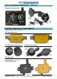
Back To TABLE OF CONTENTS TST-770 SYSTEM COMPONENTS - DISPLAY Display and Components Magnetic Display Mount 12v Power Adapter 5” Touch Screen Color Display Suction Cup Mount USB-C Cable SYSTEM COMPATIBLE COMPONENTS* * Beginning with product date code 0119 and after.
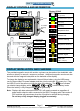
Back To TABLE OF CONTENTS DISPLAY CONTROLS AND INFORMATION LCD Color Touchscreen Display Display ICONS Antenna Tire Icon (not yet coded) Tire Programmed On Power Off (Tire Swap Location screen) Tire Normal (after coded) Tire Alert 12v USB-C Charging Port (after coded) ºF / ºC Temperature Unit PSI/BAR Pressure Unit Red LED alert light Pressure Warning Magnetic base mount plate Sensor pairing area Temperature Warning Scan QR Code for online support and documentation Sensor Low Battery Di
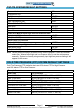
Back To TABLE OF CONTENTS TST-770 SYSTEM DEFAULT SETTINGS Pressure Unit Temperature Unit High Pressure Alert Low Pressure Alert High Temperature Alert Power Unit Cold Tire Pressure Steer Axle Drive Axle Spare Tire Power Unit Manual Input High and Low Pressure Alert High (Axle1/2/3/S) Low (Axle1/2/3/S) Trailer Cold Tire Pressure Trailer # 1/2/3/4/5 Trailer Manual Input High and Low Pressure Alert High (Axle1/2/3/S) Low (Axle1/2/3/S) PSI ºF 125 PSI 90 PSI 158ºF 100 PSI 100 PSI 100 PSI 125 PSI 90 PSI 100 PSI
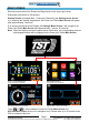
Back To TABLE OF CONTENTS MAIN SCREEN Remove protective film from Display by lifting the tab in the upper right corner. Slide power slide switch to ON position. Startup Screen will appear after ~5 seconds, followed by the Settings Icons Screen or, if sensor(s) are already programmed, the Power Unit/Trailer Main Screen will appear after approximately 5 seconds.
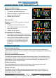
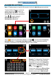
Back To TABLE OF CONTENTS UNDERSTANDING YOUR TIRE ALERTS When there is an alert, the tire position will change from yellow to red, will display the corresponding alert with icons, audible alarm will sound (beep) and LED will flash red. When you silence the alert by touching the screen, The alert will not sound again as the unit cycles back to the alert tire. The alert text continues to flash and the tire remains red. LED stays on as long as the alert is active.
Back To TABLE OF CONTENTS UNDERSTANDING YOUR TIRE ALERTS (cont.) Sensor Low Battery Alert Example: Sensor Low Battery icon shown. 1. Tire position will start flashing red. 2. Sensor Low Battery indicator and icon will flash, once every second. 3. Audible alert will sound. Fast Leak Alert Example: Loss of 2 PSI or greater in less than one minute. 1. Tire position will start flashing red. 2. FAST LEAK indicator and icon will flash, once every second. 3. Audible alert will sound.
Back To TABLE OF CONTENTS PARAMETER SETTINGS Note: If Display senses no input for 90 seconds, it will exit to Main Screen automatically. To adjust Default Settings, touch main screen settings icon to enter into Settings Menu Screen 1. This will be the first step for the remaining sections. Touch or to switch between Settings Menu Screen 1 or Settings Menu Screen 2. Power Unit/Trailer Main Screen Settings Menu Screen 1 Settings Menu Screen 2 Touch to enter into Parameters Settings.
Back To TABLE OF CONTENTS COLD TIRE PRESSURE ALERT SETTINGS - POWER UNIT The following instructions will utilize the Default High/Low Pressure Alert thresholds. For Manual High/Low Pressure Alert thresholds, go to page 13. Note: When inputting Cold Tire Pressure (CTP) with this option, High Pressure Alert will be set at 25% above CTP and Low Pressure Alert will automatically be set at 10% below CTP. To adjust Cold Tire Pressure settings, touch to enter into Pressure Alert Settings.
Back To TABLE OF CONTENTS COLD TIRE PRESSURE ALERT SETTINGS - TRAILERS The following instructions will utilize the Default High/Low Pressure Alert thresholds. For Manual High/Low Pressure Alert thresholds, go to page 13. Note: When inputting Cold Tire Pressure (CTP) with this option, High Pressure Alert will be set at 25% above CTP and Low Pressure Alert will automatically be set at 10% below CTP. To adjust default Cold Tire Pressure settings, touch to enter into Pressure Alert Settings.
Back To TABLE OF CONTENTS MANUAL HIGH/LOW PRESSURE ALERT SETTINGS Note: High Pressure Alert defaults are set at 25% above Cold Tire Pressure setting and Low Pressure Alert will be set at 10% below Cold Tire Pressure setting. To manually adjust High and Low Pressure Alert values, touch Pressure Alert Settings. Touch , , , , or Cold Pressure screen. Example: Touch .
Back To TABLE OF CONTENTS SWAP TIRE LOCATION Note: Only tires with paired sensors can be swapped. In the Swap Tire Location screen currently programmed tires will show as solid green color. Touch Touch to enter into Swap Tire Location settings. to enter Power Unit Tire Position settings. Settings Menu Screen 1 Power Unit or Trailer Selection Screen Power Unit Swap Tire Sensors Screen Swap Tire Sensors Screen Touch to select the tire you want to swap (selected tire will flash green).
Back To TABLE OF CONTENTS AUTOMATIC CODE LEARNING Touch Touch to enter into Automatic Code Learning settings. to enter Sensor Code Learning settings for power unit. Settings Menu Screen 1 Power Unit or Trailer Selection Screen Power Unit Tire Position Screen Power Unit Tire Position Screen Touch to select the tire you want to code to the sensor. Selected tire will flash white and yellow and the icon will appear on the screen.
Back To TABLE OF CONTENTS AUTOMATIC CODE LEARNING (cont.) Sensor Code Capture Screen Power Unit Sensor Code Learning Screen If sensor code learning is successful, sensor ID code (Example: C5A17B) will appear on Sensor Code Capture screen with options to Exit and Save. Note: If sensor code learning is unsuccessful, RESCAN will appear on Sensor Code Learning screen (after ~10 seconds). Touch icon to attempt to learn sensor code again. Repeat above steps until sensor is coded.
Back To TABLE OF CONTENTS SECTION INTENTIONALLY LEFT BLANK support@TSTtruck.com Page 17 (770) 889-9102 M-F 9-8pm, Sat 9-2pm EST © 2021 Truck System Technologies and Pressure Systems International Inc. All Rights Reserved Worldwide.
Back To TABLE OF CONTENTS SECTION INTENTIONALLY LEFT BLANK support@TSTtruck.com Page 18 (770) 889-9102 M-F 9-8pm, Sat 9-2pm EST © 2021 Truck System Technologies and Pressure Systems International Inc. All Rights Reserved Worldwide.
Back To TABLE OF CONTENTS CONNECT/DISCONNECT Note: This example shows Trailer Units. All connected units will show as blue icons with white text. Touch Touch to enter into Connect/Disconnect Tire settings. , , , or on the Connect/Disconnect Tire screen. Settings Menu Screen 1 Power Unit or Trailer Connect/Disconnect Screen Power Unit/Trailer Unit Disconnect Screen Power Unit/Trailer Main Screen Touch to disconnect the trailer selected. then select Exit and Save.
Back To TABLE OF CONTENTS CUSTOM VEHICLE ID Note: If Display senses no input for 90 seconds, it will exit to Main Screen automatically. To adjust Default Settings, touch main screen settings icon to enter into Settings Menu Screen 1. Touch to switch to Settings Menu Screen 2. This will be the first step for the remaining sections.
Back To TABLE OF CONTENTS CUSTOM VEHICLE ID (cont.) BOAT Full Keyboard Input Screen Full Keyboard Input Screen Enter new name for Trailer 1. Example: “BOAT”. Touch to delete character. or Touch changed. to exit Full Keyboard Input screen after vehicle ID settings are Exit and Save or Exit Without Saving Screen Power Unit/Trailer Main Screen To save your input, touch Exit and Save. To cancel, touch Exit without Saving. Selection returns you to the Power Unit/Trailer Main Screen.
Back To TABLE OF CONTENTS DATE & TIME SETTINGS Note: Default Time Zone is set to CST(UTC-06:00). Settings Menu Screen 1 Settings Menu Screen 2 Power Unit or Trailer Selection Screen Exit and Save or Exit Without Saving Screen To change your preferred Time Zone, touch to enter into Date & Time settings. Touch the preferred Time Zone in the available menu. to exit Time Zone screen. To save your input, touch Exit and Save. To Touch cancel, touch Exit without Saving.
Back To TABLE OF CONTENTS SENSOR BATTERY VOLTAGE Settings Menu Screen 2 Power Unit or Trailer Selection Screen Touch Power Unit Tire Position Screen to check into Sensor Battery Voltage. , , , , or Touch respective trailers or power unit. Touch any to view Sensor Battery Voltage readings for icon to check the sensor voltage.
Back To TABLE OF CONTENTS RESET To Reset System to Factory Defaults: Settings Menu Screen 1 Settings Menu Screen 2 Power Unit or Trailer Selection Screen Yes or No Selection Screen To reset the system to factory default settings, touch to enter into Reset screen. to Reset To Factory Default. Touch to reset to factory default Touch settings. Touch to exit without changes. Both options will return to Main Screen.
Back To TABLE OF CONTENTS ABOUT Settings Menu Screen 1 Settings Menu Screen 2 Power Unit or Trailer Selection Screen Yes or No Selection Screen To review system information, touch to enter into About screen. About menu will display current Hardware and Software Version Information. Touch to return to the Power Unit/Trailer Main Screen. support@TSTtruck.com Page 25 (770) 889-9102 M-F 9-8pm, Sat 9-2pm EST © 2021 Truck System Technologies and Pressure Systems International Inc.
Back To TABLE OF CONTENTS SENSOR INSTALLATION - CAP SENSOR 1. 2. 3. 4. Screw the hex nut onto the valve stem threads until it bottoms out. The hex nut is not required, but is provided as a theft deterrent. Theft deterrent hex nut Screw the correctly marked sensor onto the valve stem for that tire position. Tighten the sensor until the air stops leaking and the sensor bottoms-out on the valve stem. Then give it a quarter turn more to seat it.
Back To TABLE OF CONTENTS SENSOR INSTALLATION - FLOW-THRU SENSOR Note: These sensors can only be used on metal valve stems. 1. Screw the hex nut onto the valve stem threads until it bottoms out. The hex nut is not required, but is provided as a theft deterrent. 2. Screw the correctly marked sensor onto the valve stem for that tire position. Tighten the sensor until the air stops leaking and the sensor bottoms-out on the valve stem. Theft hex nut Thendeterrent give it a quarter turn more to seat it.
Back To TABLE OF CONTENTS SENSOR PREPARATION - INTERNAL SENSORS Always consult with a Certified Safety Consultant prior to any installation procedures. Read and understand all instructions and procedures before service to components begins. NOTE: Identify your Internal Sensor type using page 4 image examples and follow steps 1-4 for your specific sensor. Steps 5-9 are common.. 1. 2. Remove the wheel from the vehicle and deflate the tire. SCREW-MOUNTED SENSOR SENSOR BAND Remove the tire from the wheel.
Back To TABLE OF CONTENTS SENSOR INSTALLATION TO WHEEL - INTERNAL SENSORS IMPORTANT: Sensor should be installed 180 degrees from the tire valve stem. See Figure 5. CAUTION: MAKE SURE THE SENSOR BAND IS CORRECTLY INSTALLED ON THE WHEEL HUB AND DOES NOT MOVE LATERALLY OR ROTATE. See Figure 5. 5. Tighten the band clamp on the wheel hub. Ensure sensor does not move laterally or rotate on wheel hub. See Figures 2, 4 and 5.
Back To TABLE OF CONTENTS DUAL WHEEL INSTALLATION - INTERNAL SENSORS Always consult with a Certified Safety Consultant prior to any installation procedures. Read and understand all instructions and procedures before service to components begins. Recommended installation orientation for Internal Sensor TPMS-equipped Dual Wheel Vehicles 1. Please review the following instructions to ensure proper orientation of internal TPMS Sensors using the 180º valve stem orientation method. See Figure 1.
Back To TABLE OF CONTENTS REPLACING THE FLOW-THRU SENSOR BATTERY (CR1632) 1. Remove the sensor from the metal valve stem. 2. Using a #00 Phillip’s screwdriver, remove the two screws from the battery cover on the side of the sensor. The “+” side of the battery can now be seen. 3. 4. Specified wrench 1 Loosen the hex nut Remove the battery and check that the metal contact points in the sensor are not corroded.
Back To TABLE OF CONTENTS REPLACING THE FLOW-THRU SENSOR BATTERY (CR2032) 1. Remove the sensor from the metal valve stem. 2. Using the specified wrench, screw off the battery cover counterclockwise. The "+" side of the battery can now be seen. Take out the battery. 3. Replace with a new CR2032 battery. Be sure the “+” (positive) side is facing out. 2 Note: It is recommended that you check the voltage of the new battery before installation. It should read 3.0 volts or greater when new. 4.
Back To TABLE OF CONTENTS REPLACING THE CAP SENSOR BATTERY (CR2032) 1. Remove the sensor from the tire valve stem. 2. Use the specified wrench to open the sensor cap counterclockwise. 3. Slide the battery out of the cage sideways. Note that the (+) side is up. Replace with a new CR2032 battery. 1 Loosen the hex nut Note: It is recommended that you check the voltage of the new battery before installation. It should read 3 volts or greater when new. 4.
Back To TABLE OF CONTENTS REPEATER The repeater is an integral component to your TPMS system. Failure to install the repeater could void the warranty coverage. The repeater is used to strengthen/amplify the sensor signal to the display. A repeater is packaged with this system. 1. The repeater is wired to a 12V source that will be constant while driving. 2. The repeater comes with two wires, one red (+) and one black (-).
Back To TABLE OF CONTENTS TROUBLESHOOTING TIPS How long should I initially charge the internal battery? The display comes partially charged but you should charge the display, using the included charging components (USB-C cord and 12v adapter), for 4-5 hours. See page 5 Why am I am having trouble seeing the screen to program it? You must remove the protective screen cover before using the display. Locate the tab in the upper right-hand corner of the screen protector and pull the protector off.
Back To TABLE OF CONTENTS TROUBLESHOOTING TIPS Is there a way to get the six-digit sensor code from the monitor? Yes. On the same screen you see the sensor battery voltage, the sensor code will appear next to the voltage readout. Tap on the tire you want to see the sensor code for. See page 23 Is there a way to reset the display and start over with the programming? Yes. Tap on the “Settings” icon on the lower left on the home screen. On the next screen tap on the left or right arrows.
Back To TABLE OF CONTENTS TROUBLESHOOTING TIPS To set up Tag Axle pressure, tap on “Pressure Alert Settings” then tap “PWR Unit” then tap “Manual Input High- and Low-Pressure Alert”. From there, put in the High-Pressure PSI (25% above cold tire pressure) and the Low-Pressure PSI (10% below cold tire pressure) in the area marked Axle 3. That will correspond to your tag axle position on the screen.
Back To TABLE OF CONTENTS SENSOR SPECIFICATIONS Operating Temperature Range Storage Temperature Range Pressure Range Pressure Accuracy Range (w/digital gauge) Temperature Accuracy Range Transmission Power Transmission Frequency Approximate Battery Life Physical Sensor Size - Flow-Thru (CR1632) Physical Sensor Size - Flow-Thru (CR2032) Physical Sensor Size - Cap Physical Sensor Size Internal Screw-mounted Physical Sensor Size Internal Belt-mounted Physical Sensor Size - Hybrid Cap Sensor Weight - Flow-Thru
Back To TABLE OF CONTENTS S2 S1 PROGRAMMED SENSOR REFERENCE DIAGRAM After pairing your sensors, you may record their 6 digit code (or sensor number) by wheel position using these Power Unit and Trailer diagrams. S1 POWER UNIT S2 This allows you to know which sensor is programmed to which tire position at a glance. TRAILER #1 S2 S1 TRAILER #2 S2 S1 TRAILER #3 S2 S1 TRAILER #4 TRAILER #5 support@TSTtruck.
Back To TABLE OF CONTENTS S2 S1 Important Notice This device complies with part 15 of the FCC rules. Operation is subject to the following two conditions: (1) this device may not cause harmful interference, and (2) this device must accept any interference received, including interference that may cause undesired operation. Changes or modifications not expressly approved by the party responsible for compliance could void the user's authority to operate the equipment.
DISCLAIMER This system is designed to monitor air pressure and temperature within the tire. It is only for added information and not meant to replace regular tire maintenance and reasonable care when operating a motor vehicle.