User’s Manual DuraLabel 7000 Rev. A, 05.
FCC COMPLIANCE STATEMENT FOR AMERICAN USERS This equipment has been tested and found to comply with the limits for a CLASS A digital device, pursuant to Part 15 of the FCC Rules. These limits are designed to provide reasonable protection against harmful interference when the equipment is operated in a commercial environment.
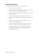
Safety Instructions Bitte die Sicherheitshinweise sorgfältig lesen und für später aufheben. 1. Die Geräte nicht der Feuchtigkeit aussetzen. 2. Bevor Sie die Geräte ans Stromnetz anschließen, vergewissern Sie Sich, dass die Spannung des Geräts mit der Netzspannung übereinstimmt. 3. Nehmen Sie das Gerät bei Überspannungen (Gewitter) vom Netz. Das Gerät könnte sonst Schaden nehmen. 4. Sollte versehentlich Flüssigkeit in das Gerät gelangen, so ziehen sofort den Netzstecker.
Safety Instructions Please read the following instructions seriously. 1. Keep the equipment away from humidity. 2. Before you connect the equipment to the power outlet, please check the voltage of the power source. 3. Disconnect the equipment from the voltage of the power source to prevent possible transient over voltage damage. 4. Don’t pour any liquid to the equipment to avoid electrical shock. 5. ONLY qualified service personnel for safety reason should open equipment. 6.
1. BARCODE PRINTER .................................................................................... 5 1-1. Printer Accessories ......................................................................................................... 5 1-2. General Specifications .................................................................................................... 5 1-3. Communication Interface ................................................................................................ 7 1-4.
1. Barcode Printer 1-1. Printer Accessories After unpacking, please check the accessories that come with the package, and store appropriately. Barcode printer Power cable USB Cable Label Roll Sample Ribbon Empty Ribbon Roll Quick Start Guide CD (includes label editing software QLabel / Manual) 1-2.
Serial port: RS-232 ( Baud rate : 4800 ~ 115200 , Xon/Xoff , DSR/DTR ) USB port: V2.0 CF card socket Back-lit LCD Display:128x64dots Graphic LCD. Control Panel Three single-color LED lamps: Power, Ribbon, Media Three control keys: FEED, PAUSE, CANCEL 100/240VAC, 50/60 Hz Power Real Time Clock Standard Operation: 41°F to 104°F (5°C to 40°C) Environment Storage: -4°F to 122°F (-20°C to 50°C) Operation: 30-85%, non-condensing. Free air. Humidity Storage: 10-90%, non-condensing. Free air. Cert.
1-3. Communication Interface Parallel Interface Handshake Interface cable Pin out PIN NO.
USB Interface Connector Type : Type B PIN NO. 1 2 3 4 FUNCTION VBUS D- D+ GND PS2 Interface PIN NO. 1 2 3 4 5 6 FUNCTION DATA N/C GND VCC CLOCK N/C PS2 interface from PC to printer Printer Keyboard DATA 1 1 DATA N/C 2 2 N/C GND 3 3 GND VCC 4 4 VCC CLOCK 5 5 CLOCK N/C 6 6 N/C Internal Interface UART1 wafer N.C TXD RXD CTS GND RTS E_MD RTS E_RST +5V GND +5V UART2 wafer N.C TXD RXD CTS GND RTS N.C RTS N.
Applicator wafer +5V +24V Printing (out) Print error (out) Printed (out) Print (in) GND N.C GND N.
1-4. Printer Parts Appearance 4 1 3 2 1. 2. 3. 4. Control panel Cutter Observing Window Top Cover 1 2 3 4 5 6 7 1. Fan-Fold Label Insert 2. CF Card Slot 3. Serial Port * 4. USB Port 5. Power Socket 6. Power Switch 7. Fan-Fold Label Insert * The communication ports may vary depending on product types.
Internal 7 8 1 9 10 2 3 13 4 11 5 12 14 6 1. 2. 3. 4. 5. 6. 7. 8. 9. 10. 11. 12. 13. 14. Ribbon Rewind Shaft Ribbon Supply Shaft TPH Spring Box Cutter Module Print Head Lever Sensor Knob Label Alignment Guide Label Supply Guide Label Roll Bar RFID Module Label Tension Plate Label Guide Printing Mechanism Platen 1 2 1. 2.
Control Panel 1 2 3 4 5 6 7 10 9 8 1. 2. 3. 4. 5. 6. 7. 8. 9. 10.
2. Printer Installation DuraLabel 7000 is a Thermal Transfer mode printer. When printing, ribbon must be installed to transfer the print contents onto the media. It supports RFID tag reading function that can detect the type of label used for printing. To ensure the best quality of printout, please use the designated label for printing. 【Note】The printer will stop the printing procedure when a non-designated label has been detected to be used for printing. 2-1. Label Installation 1.
4. Pull the Label Alignment Guide to the direction as the blue arrow 1 indicates. 5. Flip the Label Supply Guide upward as the blue arrow 2 indicates. 5. 6. 2 1 Place the label roll onto the Label Roll Bar and align the label to printer’s inner wall. (To avoid the damage of media, please do not squeeze the label roll too hard.) 2 1 Pull the Label Alignment Guide back and make it fit the edge of label roll. 【Note】 Please always hold the bottom of the Label Alignment Guide when moving. 7.
9. Align the label edge inward, and fix the label outside in Label Guide. Adjust the Label Guide with the label. 【Note】 The Label should be put within Label Feed Guide as the figure shows. 10. Flip the Print Head Lever back to its original position. 11. Close the cutter and top cover to complete the label installation.
2-2. Ribbon Installation 1. Place the printer on a horizontal surface, and open the top cover. 2. Follow the sequence and direction as the figure shows, pull the Print Head Lever out and flip it upward to the right. 3. Press the Cutter Hook to open the cutter. 4. Place a new ribbon roll onto the Ribbon Supply Shaft and place the empty ribbon roll onto the Ribbon Rewind Shaft. 5. The right-bottom figure shows two different installing directions according to different types of ribbons.
6. Feed the ribbon from the Ribbon Supply Shaft under the print head. Wrap the ribbon around the Ribbon Rewind Shaft and stick it onto the empty ribbon roll. 【Note】 DO NOT feed the ribbon under the Moveable Sensor.
2-3. PC Connection 1. 2. 3. 4. Please make sure the printer is powered off. Take the power cable, plug the cable switch to the power socket, and then connect the other end of the cable to the printer power socket. Connect the cable to the USB/parallel port on both side of printer and PC. Power on the printer, the LCD display would show the printer model and F/W version.
2-4. Driver Installation 1. Once the USB cable is connected from PC to the printer, PC will automatically detect the new device and begin the installation process. 2. Insert the product CD, select ‘Specify a location’ and describe the path of the printer driver. 3. Follow the instruction on the Window and complete the driver installation.
3. Control Panel 3-1. Control Panel Introduction Control keys FEED PAUSE CANCEL LED indicators Power Ready(Power) Power on After turning on the power, the Ribbon and Media lights will flash alternately until the completion of initialization. Ribbon Ribbon status indication Media Media status indication 3-2. Control Keys Introduction FEED Key After pressing the FEED key, printer will send the media (according to media type) to the specified stop position.
Item Key Self test Beep LCD Message + Power 3 beeps + Power 3 beeps Æ 1 beep Now in Dump Mode 3 beeps Auto sensing Mode 2 beeps twice Go to default 1 beep DL MODE Vx.xx 3 beeps Setting mode Self test on Dump mode on Auto sensing on Go to default + Power on Download mode + Power + + Power on Setting mode DuraLabel 7000 User’s Manual 21 Description key and turn Press and hold on the printer until the buzzer beeps 3 times.
3-3. Setting mode In the Setting Mode, changes can be made according to requirement on the printing mode, options, media type, and parallel interface (printer can only go into setting when connected to PC by parallel cable, USB cable, or serial cable). 1. 2. 3. Power on the printer and make sure it is on “Ready to print” status. Press and hold Pause key about 3 to 4 seconds until the buzzer beep 3 times (for product types that with LCD monitor, the LCD will display “Setting Mode”).
Below are general descriptions of setting items. Default: 15 Set the darkness of printing result. The setting value is from Darkness 0 to 19 and the default value is 15. Show the speed of printing. The default value is 2(IPS). Speed Default: 0 Adjust Stop Position Set the stop position of printing. The setting value is from 0 to 10. Default: 0 Printhead Position Set the position of print head when printing. The setting value is from -100 to 100.
Keyboard Setup Keyboard Mode Buzzer Setup Smart Backfeed Password Top of Form Ethernet Preview Default: US US UK French German Spanish Italian Finnish Dutch Belgian Default: Recall Label Recall Label:Recall label from memory card. Keyboard Setup:Setting the keyboard. Code page Setup:Setting the code page. Printing Option: Set the print quantity. Clock Setup: Set the clock and clock display. Exit KB Mode:Exit PS2 KB Mode. Default: ON ON OFF Default: ON ON: This function must install stripper or cutter.
The diagram of Setting Mode Adjust Stop Position Speed Darkness 0 ~ 10mm 2 0~19 OFF Spanish Traditional Chinese German Italian Stop Bits Italiano Finnish Deutsch Dutch Fran çais Belgian Clock Display Clock Setting Clock Setup Printer Prompts Printing Option Code Page 850* Indefinite Fixed Code page 852 Code page setup Espa ñol Press and hold Pause key about 3 to 4 seconds until the buzzer beep 3 times and LCD shows “Setting mode”.
3-4. Self-Test The Self-Test function will help user to check whether the printer is operating normally. In Self-Test Mode, the printer will print out a test sample each time when the FEED key is pressed. To break off the Self-Test procedure, please power off the printer. Below are the Self-Test procedures: 1. 2. 3. Power off the printer, press and hold the FEED key. Power on the printer (while still holding the FEED key); release the FEED key after hearing 3 beeps.
3-5. Dump Mode When label setting and the print result don’t match, it’s recommended to go into the Dump Mode to check whether there’s a mistake in data transmission between the printer and the PC. For example, when printer receives 8 commands, yet without processing these commands, only printed out the contents of the commands, this will confirm whether the commands were received correctly. Test procedures to enter the Dump Mode are as follows: 1. 2. 3. 4.
3-7. Error Messages If problems occur that prevent the printer printing normally, the printer will beep as warning, and error messages will be displayed. Quickly blinking LCD Message Display Slowly blinking LED Message Light Ribbon Beep Light is on Description Solution Thermal Print Head is not firmly closed. Thermal Print Head temperatur e high. Ribbon not installed, and printer shows error message. Ribbons used up or ribbon supply shaft not moving.
Memory Full 2 beeps twice Memory is full Rewinder Full 2 beeps twice Rewinder is full Filename can not be found 2 beeps twice Can’t find the file Filename repeated 2 beeps twice File name is repeated DuraLabel 7000 User’s Manual 29 Delete unnecessary data in the memory or use CF Card. Remove the labels on rewinder. Use “~X4” command to print out all the files, then check whether the file exist and the names are correct. Change the file name and download again.
4. Accessory 4-1. Cutter Installation 1 Cutter Module 2 Lock*2 3 Screw*2 【Note】 To install the Cutter Module, please power off the printer first. 1 2 3 1. Open the Top Cover and unscrew two screws in the front to remove the Tear-off bar. 2. Hold the Cutter Module and secure with screws to install it on printer. 3. Plug the cutter cable into the cutter connector. 4. Tie the cables with secure lock, and stick the lock on the Bottom Plate. 5. Load the label to the printer.
4-2. Cutter Operation The cutter module is a factory default accessory, hence it is necessary to open the cutter module in some printer operations, such as loading the label or ribbon. To open the cutter module, please press the Cutter Hook and flip the cutter downward as shown in below figure. 【Caution】Although essential precautions have been adopted for the protection, it is still necessary to be careful when touching, installing, removing, operating and cleaning the cutter module.
4-3. Clean the Cutter 1. Unscrew the screws to remove the top cover of cutter module. 2. Clean the edge of knife with cotton swab and alcohol. 3. Assemble the top cover back to the cutter module and tighten the screws.
4-4. Parallel/PS2 Adapter Installation 1 2 3 4 Parallel Cable Parallel/PS2 Adapter Connector Cable Screw x 2pcs 1 2 3 1. Make sure the power is off and the power cable is unplugged. Place the printer onto a smooth surface and open the top cover. 2. Unscrew two screws as indicated in figure and remove the left top cover from the printer. 3. Unscrew the screws of parallel port cover and remove the cover.
4. Align the Parallel/PS2 module to the parallel port and secure the module onto the back plate. 5. Connect one end of the 30 pin connector cable to the main board and the other end to the Parallel/PS2 module. 6. The Parallel/PS2 module installation is complete.
5. Maintenance and Adjustment 5-1. Print Head Module Installation / Removal Instruction 1. Open the top cover. 【Note】 Please power off the printer before removing the print head module. 2. Press the Cutter Hook to open the cutter. 3. Pull the Print Head Lever out and flip it upward to the right. 1 2 4. To remove the print head module, hold on the front of the print head module and pull it out.
5. If user cannot successfully remove the print head by hand, the screwdriver can be used for assistant as the figure shows. 6. To install the print head module, hold on the front of the print head module and slide down along the track. Align the male end (with protruding pins) with the female end (pin base) and push the print head module down.
5-2. TPH Print Line Adjustment Please contact your local dealer for technical support if it is necessary. 1. Open the top cover. 2. Press the Cutter Hook to open the cutter. 3. Pull the Print Head Lever out and flip it upward to the right.
4. TPH print line adjustment: When the printing is stiff or printing with thick paper, the print line needs to be moved forward (paper feed direction) in order to achieve better printing quality. Use a flat tip screwdriver, and turn the screws (A) clockwise to move the TPH forward TPH position adjustment for the left and right screws (A) need to be identical to make sure that the print line and the roller platen are parallel to each other. Turning the screws (A) one circle, the TPH will move 0.
5-3. Ribbon Tension Adjustment The ribbon shaft tension can be adjusted by turning the ribbon shaft knob clockwise or counterclockwise. There are 4 different levels of tension and marked with 1~4 on both knobs of Ribbon Rewind Shaft and Ribbon Supply Shaft. 1 represents the strongest tension and 4 is the weakest tension. When the tension is too weak to pull the ribbon, please decrease the tension of Ribbon Supply Shaft or increase the tension of Ribbon Rewind Shaft.
5-4. Thermal Print Head Cleaning Unclear printouts (some parts of label cannot be printed) may be caused by dusty print head, ribbon stain, or label liner glue. Therefore when printing, it’s necessary to keep the top cover closed. Also, check and prevent paper/label from being stained or dusty to ensure print quality and to prolong the print head life. Print head cleaning instructions are as follows: 1. 2. 3. 4. 5. 6. Power-off the printer. Open the top cover. Take out the ribbon. Open the cutter module.
5-5. Print Head Balance and Pressure Adjustment 1. Open the top cover. 2. Pull the Print Head Lever out and flip it upward to the right. 1 2 When printing with different label materials or using different ribbon types, unbalanced print quality may occur due to the media material differences. Moreover, when one side of the printout is not printed clearly or ribbon wrinkle occurs, it’s necessary to adjust the position or pressure of TPH Spring Box. 3.
5-6. Ribbon Shield Adjustment 1. Due to the differences in the ribbon materials, if ribbon wrinkles occur during printing, please adjust the ribbon shield screw. Example: If ribbon wrinkles occur as (a), please turn the ribbon shield screw A clockwise, and if ribbon wrinkles occur as (b), please turn the ribbon shield screw B clockwise. (a) 2. (b) It is recommended to adjust by a half of a circle each time to fully control the printing quality and status.
5-7. CF Card Instruction DuraLabel 7000 has built-in CF Card slot on the back of the printer. If the built-in memory is insufficient for storing label formats, graphics or fonts, users can use CF Card as external memory to provide more memory space. When using the CF card, please follow the instruction as below: 1. 2. 3. 4. 5. Please power off the printer before installing or removing CF Card from the card slot. The CF Card cannot be used for printer’s external memory until it is formatted in FAT16.
5-8.