OPERATION MANUAL GodexLAN for Wireless LAN & Ethernet Module Operation Manual : GodexLAN Version : Rev. E Issue Date : 2012.07.
1. PRODUCT OVERVIEW ............................................................................ 1 1-1. General Description .......................................................................................................................... 1 1-2. Ethernet Module Specifications......................................................................................................... 2 1-3. Wireless LAN Module Specifications ................................................................................
1. Product Overview 1-1. General Description Network Printer Server is designed to connect your printers to your network, allowing all network users access to these shared printers. This Server provides the following features and benefits: Reliability: The Server provides high performance and reliability combined with low power consumption. Flexibility: The Server supports print sharing in all major computer systems and environments.
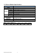
1-2. Ethernet Module Specifications ITEM CPU SDRAM Flash Memory Connector Standard Protocol ETHERNET Server Setup Security Connector USB Port Standard POWER LED LAMP ENVIRONMENT DIMENSIONS WEIGHT OTHERS Description 32-bits RDC(x86), 133 MHz 4M Bytes 2M Bytes RJ-45 Connector IEEE 802.3 10/100Base-Tx (Auto-Sense) ARP, IP, UDP, TCP, HTTP, DHCP, FTP, SNMP, SMTP TCP Server ; UDP Server HTTP Browser Setup (IE & Netscape) Setup Password & Connect Password Dual row 8-pin header USB 2.
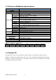
1-3. Wireless LAN Module Specifications ITEM CPU SDRAM Flash Memory Standard Description 32-bits RDC(x86) , 133 MHz, miniPCI 16M Bytes 2M Bytes IEEE 802.11b/g, 2.4GHz, DSSS 802.11b : 1, 2, 5.5, 11 Mbps Data Speed 802.11g : 6, 9, 12, 18, 24, 36, 48, 54 Mbps Network Infrastructure, Ad-Hoc TX Power 802.11b : ~15 dBm; 802.11g : ~12 dBm 802.11b : -80 dBm@11 Mbps, Packed Error Rate 8% RX Sensitivity 802.
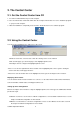
2. The Control Center 2-1. Get the Control Center from CD 1. Insert the included CD into the personal computer. 2. Go to "Control Center" folder and double click the "Setup Control Center.exe" icon to install the program to your personal computer. 3. After the installation is completed, please click the "Control Center" icon to start the program. 2-2.
2-3. System menu System: Select the "Exit" item to close the Control Center. Tools: Select "Configuration" item to configure the Control Center. The configuration includes server information setting and language setting. Help: To display the version information of Control Center. Quitting the Control Center There are two ways to close the Control Center. The first way is clicking the “X” box (close box) at the top right corner of the window.
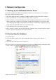
3. Network Configuration 3-1. Setting up Local Windows Printer Driver You are advised to install your Windows printer driver in advance. For most printers, you can install the printer drivers with the following procedure: 1. Click Start, click Control Panel, click Printers and Other Hardware, and then click Printers and Faxes. 2. Double click Add Printer to start the Add Printer Wizard, and then click Next. 3.
On "Port Settings", change the "Protocol" to "LPR". And the "Queue Name" setting must be "USB1_LQ" to connect your printer properly. 3-3. Wireless Connection 3-3-1. Preliminary Before you can access wireless network, wireless parameters should be set correctly. You have to setup the first wireless parameter set through LAN (wired) connection. Wireless access can be set as: 1. Infrastructure (station) mode, which need an access point to route network messages, or 2.
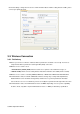
3-3-2. Set Wireless Configuration Using Network Printer Server Control Center 1. Install the "Control Center" program to your PC. Network Printer Server Control Center is available in the product CD of Ethernet or Wireless LAN module. 2. Start the Network Printer Server Control Center and an Auto-searching Network Printer Server window will appear. *If the wireless parameters are not correct or not set yet, you have to use LAN to access Network Printer Server. 3.
5. After you login successfully, from the Server menu, select wireless. The set Wireless dialog appears. 6. In order to join an existing wireless network, you have to set the correct network type (infrastructure or ad-hoc), SSID, and the correct security method with the correct key information. *Please check with your Network Administrator about network setting if necessary. 7. If the wireless network is secured by WEP64 or WEP128, authentication method, key index, and WEP key must be set correctly. 8.
9. Click Apply to save your settings. And the server will reboot. 10. You have now finished the procedure of setting the wireless parameters. *In infrastructure mode, Network Printer Server Control Center searches all channels to join the matched wireless service set.
4. After you have logged in successfully, the first configure page will be General Configuration of printer server. 5. To proceed the wireless configuration, click the "Configuration" icon.
6. Click "WLAN" icon. 7. In order to join an existing wireless network, you have to set the correct network type (infrastructure or ad-hoc), SSID, and the correct security method with the correct key information. 8. If the wireless network is secured by WEP64 or WEP128, key index and WEP key must be set correctly. 9. If the wireless network is secured by WPA-PSK/TKIP, the shared key must be set correctly.
10. Click Submit to save your settings. And the server will reboot. 11. You have now finished the procedure of setting the wireless parameters. *In infrastructure mode, Network Printer Server Control Center searches all channels to join the matched wireless service set.
3-4. Assigning an IP Address to the Server 3-4-1. Preliminary If you have a DHCP server on your network, your Server will receive an IP address automatically. The IP address will then appear on the Control Center or on the page of configuration report. If your DHCP server does not give an IP address to the Server, the Server will use the Factory IP address. If you are not working in a DHCP network, you need to manually set the Server’s IP address.
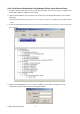
3-4-2. Setting the IP Address Using the Control Center 1. Start the Control Center and Auto-searching Server window will appear. 2. If the tool finds print servers in your local area network, then you have to select one server from the Server List. 3. Double click the highlight list and enter the Server’s administrator (default: admin) and password (default: admin). 4. After you have logged in successfully, select TCP/IP from the Server’s menu. The Set IP Address dialog appears.
5. Click the button corresponding to your choice of IP setting method (static or dynamic using DHCP). When assigning a static IP address you also have to define Subnet Mask and Default Gateway. If you choose "Automatically get IP by DHCP", you can use desired DNS by clicking the Manual DNS button and manually assigning a DNS. 6. Click Apply to save your settings. And the Server will reboot. 7. You have now finished the procedure of setting the IP address.
3-4-3. Setting the IP Address Using the Server’s Web Pages 1. If you don’t know the current IP of you Server, you have to do the Step1~Step4 of Set the IP Address Using the Control Center. 2. You can see the IP address of you Server in the Server List. Open IE Browser and enter the Server’s IP address or click the “Go to Homepage” button in the Control Center. 3. Go to the web page and click "Login" link. 4. Login your administrator (default: admin) and password (default: admin). 5.
6. Click the "Configuration" icon. 7. Click TCP/IP icon. 8. Click the button corresponding to your choice of IP setting methods (static or dynamic using DHCP). When assigning a static IP address you also have to define Subnet Mask and Default Gateway. 9. Click Submit to save your settings. And the Server will reboot. You have now finished the procedure of setting the IP address.
4. The Server’s Web Pages 4-1. Introduction The Server runs the daemon of http server, httpd on TCP port: 9100. Users may use the web pages to see the Server’s system status and configure the Server. 4-2. Using the Server’s Web Pages 4-2-1. Displaying Server Status You can see the status of Printer, Server, TCP/IP and Wireless.
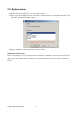
4-2-2. Setting up Server Configuration To set up the Server configuration, the system will request user to enter administrator (default: admin) and password (default: admin) to login. User Accounts: You can change administrator name and password or add a user account for print server. If you forgot administrator name and password, you must perform Restore Factory Default action. Please refer to the chapter “Restore Factory Defaults”.
Alert Message Filter: Enable or disable the options to send error messages via Auto-Mail or SNMP. SNMP: This Server runs an SNMP daemon supporting SNMP v1 and v2c protocols (Simple Network Management Protocol).
manage the Server. The Server supports all relevant parts of MIB-II and a private MIB. You can set these MIB variables from the Server’s web pages or by using the Control Center. You can set community and some parameters for SNMP server. The SNMP Configuration includes: Authentic Community: set Community name of SNMP server. Trap Community: set Trap Community name for SNMP server to send trap packets. Trap Address (IP): enter an IP address to send the Trap packet.
Maintenance If you want to restore factory default values of the Server and upgrade new firmware of Ethernet/Wireless LAN or printer, you can use the Maintenance tool: Printer Firmware Upgrade: click Open to find the firmware file to be upgraded. Click Upload to upload the firmware into the printer. Server Factory Default: click this button, the Server will restore factory default values. Server Firmware Upgrade: click Open to find the firmware file to be upgraded.
Printer Control Input printer's command language in "Input Command" window and press Enter key, the server will then transfer a line of commends to printer. If sent command returns response message, the message will be displayed in "Output Message" window. Diagnosis The Diagnosis function can check the hardware status of printer. Click "TPH Resistance" button to check the bad dot information of Thermal Print Head. The checking result will be displayed in "Output Result" window.
Alert Message Collect and display the error message that come from the printer. You can click "Dump" button to get printer's error message and display it on Alert Message window. Click "e-mail" to send the message to designated mail address or click "Clear" to remove the message. *Note: The all alter messages will be removed out from the memory when click “Dump” button.
Support Display the contact information of technical support.
5. Troubleshooting This chapter provides useful information to help you resolve difficulties that you may experience with your Server. Fault symptoms, possible causes, and remedial actions are provided within a quick reference table. 5-1.
6. Restore Factory Defaults 1. Go to the Server’s web page and click Login 2. Enter administrator (default: admin) and password (default: admin). 3. Click Maintenance. 4. Click Server Factory Default. 5.
7. Upgrade Server Firmware *Note: Failure of server firmware loading or upgrading may cause damage to the Ethernet/Wireless LAN module. Please follow below procedures for loading and upgrading firmware, or please seek help from your network administrator. This chapter describes how to upgrade firmware. Please follow the following procedure: 1. Power on the Server. Suppose that the Server is in DHCP mode. 2. Check the Server's IP address. 3. First, run Control Center.