EZ1105 / EZ1305 BARCODE PRINTER USER MANUAL USER MANUAL VERSION ISSUE DATE P/N : EZ1105 / EZ1305 : Rev. C : 2013.07.
FCC COMPLIANCE STATEMENT FOR AMERICAN USERS This equipment has been tested and found to comply with the limits for a CLASS A digital device, pursuant to Part 15 of the FCC Rules. These limits are designed to provide reasonable protection against harmful interference when the equipment is operated in a commercial environment.
Safety instructions Please read the following instructions carefully. 1. Keep the equipment away from humidity. 2. Before you connect the equipment to the power outlet, please check the voltage of the power source. 3. Make sure the printer is off before plugging the power connector into the power jack. 4. It is recommended that you connect the printer to a surge protector to prevent possible transient overvoltage damage. 5. Be careful not to get liquid on the equipment to avoid electrical shock.
1. BARCODE PRINTER ........................................................................................ 1 1-1. Box Contents .......................................................................................................................1 1-2. Specifications ......................................................................................................................1 1-3. Interfaces ...........................................................................................................
1. Barcode printer 1-1. Box Contents Please check that all of the following items are included with your printer: Barcode printer Power cord AC adapter USB cable Label stock Ribbon Empty ribbon core Label supply hub Label guide plates (set of 2) Quick reference guide CD (with QLabel label software / user manual) 1-2.
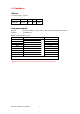
Barcodes Code Pages Graphics Interfaces Control Panel Power Environment Humidity Agency Approvals 1-D Bar codes: Code 39, Code 93, Code 128 (subset A, B, C), UCC/EAN-128 K-Mart, UCC/EAN-128, UPC A / E (add on 2 & 5), I 2 of 5, I 2 of 5 with Shipping Bearer Bars, EAN 8 / 13 (add on 2 & 5), Codabar, Post NET, EAN 128, DUN 14, HIBC, MSI (1 Mod 10), Random Weight, Telepen, FIM, China Postal Code, RPS 128 and GS1 DataBar 2-D Bar codes: PDF417, Datamatrix code, MaxiCode, QR code and Micro QR code CODEPAGE 437,
1-3. Interfaces USB port Connector type : Type B Pin No. 1 2 3 4 Function VBUS D- D+ GND Serial port (optional) Default settings : Baud rate 9600, no parity, 8 data bits, 1 stop bit, XON/XOFF protocol and RTS/CTS RS232 housing (9-pin to 9-pin) DB9 socket --1 RXD 2 TXD 3 DTR 4 GND 5 DSR 6 RTS 7 CTS 8 RI 9 Computer 1 2 3 4 5 6 7 8 9 DB9 plug +5V, max 500mA TXD RXD N/C GND RTS CTS RTS N/C Printer 【Note】 The total current to the serial port may not exceed 500 mA.
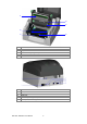
1-4. Getting to know your printer 1 2 3 5 4 1. 2. 3. 4. 5. 6. 6 Release buttons for opening the printer cover Printer cover Label supply hub Ribbon feed mechanism Print mechanism Holder for ribbon rewind core 1 2 4 5 3 1. 2. 3. 4. 5.
1 4 5 2 6 3 1. 2. 3. 4. 5. 6. Print head Label guides Paper feed roller Screw for adjusting the print line Holder for ribbon supply core Label sensor 1. 2. 3. 4. 5. 6.
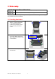
2. Printer setup This printer supports the following printing methods: Thermal transfer Requires a ribbon for transferring a printed image to a medium. printing (TTP) Direct thermal Does not require a ribbon, only thermal paper. printing (DTP) Please check which printing method you are using and alter the settings accordingly in the printer driver and/or software. 2-1. Loading the ribbon 1. Place the printer on a flat surface.
4. Install a new ribbon by placing first its right-hand side and then its left-hand side on the holder at the back. 【Note】 When installing the ribbon and empty core, please make sure to align them so the lug on the holder slots into the notch on the ribbon core. 5. Pass the ribbon under the print head. 6. Attach the ribbon to the empty core with the adhesive strip at the end of the ribbon. 7. Turn the ribbon feed mechanism to tighten the ribbon until it has no wrinkles. 8.
2-2. Loading the label roll 1. Open the printer cover by pressing the release buttons on both sides of the printer housing and lifting the cover. 2. Place the label roll on the label supply hub. 3. Release the print mechanism and lift it. 4. Pass the labels through the paper guides up to the tear-off plate. 5. Adjust the paper guides to the label width. 6. Close the print mechanism.
2-3. Installing the label supply hub (A) Installing the label supply hub for 1" cores (B) Installing the label supply hub for 1.
2-4. Connecting the printer to the host computer 1. 2. 3. 4. Please make sure that the printer is switched off. Connect the power cord to the AC adapter and connect the adapter to the printer. Connect the USB / parallel cable to the printer and host computer. Switch on the printer. The operator panel should now light up.
2-5. Installing the driver 1. Insert the product CD in the CD/DVD drive of the host computer and open the "Windows Drivers" folder on the CD. 2. Select the icon for the driver file and click it to start the installation. 3. Follow the instructions on the screen. The Driver Wizard guides you through the installation procedure. 4. Select "Install printer drivers". 5. Specify your printer model.
6. Specify the port used to connect the printer to the host computer. 7. Enter a printer name and assign the appropriate rights. 8. Once the installation is complete, a summary of the printer settings is displayed. 9. Check whether the printer settings are correct and click "Finish" to start copying the driver files. 10. Wait until copying is complete, then finish the installation. 11. Once the driver installation is complete, the new printer should appear in the "Printers and Faxes" folder.
3. Operator panel 3-1. FEED button When you press the FEED button, the printer moves the label to the defined stop position. If you are using continuous labels, pressing the FEED button will move label stock until you release the button again. If you are using individual labels, pressing the FEED button will move only one label. If the label does not stop at the correct position, you need to run the auto-detection function on the label stock (see Section 3-3). 3-2.
3-4. Self test The self-test function lets you check whether the printer is functioning normally. The contents of a self-test printout are listed below.
3-5. Error alerts The table below lists the error alerts you may see in the event of a problem that prevents normal functioning of the printer, allowing you to identify and correct the problem. Flashing frequency Colour LED indicator Fast flashing Slow flashing Red Orange Description Light on Solution Unable to detect the Run the auto-detection function paper. again. The ribbon or labels are Replace the ribbon or label roll. finished. Possible reasons: The paper feed roller is blocked. Paper jam.
4. Accessories 4-1. Installing the RS-232 module (serial port) 1 Module connection cable 2 RS-232 module (serial port) 3 Fastening screw 4 RS-232 bracket 【Caution】 Please make sure that you take precautions to prevent electrostatic discharge during the installation. 1. Make sure that the printer is switched off and the power cord disconnected from the printer. You should work on a clean, flat surface.
7. Remove the two hex screws on the left and right of the RS-232 module (serial port). 8. Push the RS232 module through the opening of the RS232 bracket supplied. 9. Secure the RS-232 module using the hex screws you removed earlier. 10. Now plug the other end of the connection cable into the motherboard socket. 11. Return the motherboard to its original position (before the installation). Please make sure that the screw holes are not covered by cables or the motherboard. 12.
4-2. Installing the Ethernet module 1 2 3 4 5 6 7 Ethernet cable, 1.8 m Ethernet module Connection cable (module to motherboard) Motherboard back panel Fastening screw (1 screw) Hex spacer (female) Hex spacer (male) 【Caution】 Please make sure that you take precautions to prevent electrostatic discharge during the installation. 1. Make sure that the printer is switched off and the power cord disconnected from the printer. You should work on a clean, flat surface.
5. Secure the motherboard back panel supplied with the printer using the back panel fastening screw and the earthing screw. 6. Using the male hex spacer, secure the female hex spacer on the motherboard in the position shown. 7. Align the Ethernet module with the new motherboard back panel as shown in the illustration. 8. Secure the Ethernet module on the motherboard using the fastening screw. 9. Plug one end of the connection cable into the motherboard and the other end into the Ethernet module.
10. Align the round opening on the Ethernet module with the round opening on the motherboard and return the motherboard to its original position (before the installation). 11. Replace the bottom part of the printer housing as shown in the illustration. 12. Secure the printer housing using the three screws you removed earlier. 【Note】 Once you have finished installing the Ethernet module, the command "^XSET,USBETHERNET,1" must be sent to the printer to enable the Ethernet module.
5. Maintenance and adjustment 5-1. Cleaning the print head Dust or dirt on the print head may result in inadequate print quality. The printer cover should therefore always be closed during printing. Please also make sure that there is no dust or dirt on the print medium you wish to use, to ensure a good print quality and print head performance. Here is how you clean the print head: 1. 2. 3. 4. 5. Switch off the printer. Open the printer cover. Release the print mechanism and lift it. Remove the ribbon.
5-3. Adjusting the print line When the print line is incorrectly set, the print quality on one side of the medium may suffer. 1. 2. A To move the print head in direction A as indicated by the blue arrow, turn the adjustment wheel anticlockwise (see arrow 1). 1 B To move the print head in direction B as indicated by the blue arrow, turn the adjustment wheel clockwise (see arrow 2).
5-4. Troubleshooting Problem Solution The printer is switched on but the LED does not light up. ♦ Check the power supply. ♦ The LED lights up red and printing is interrupted. ♦ Check the software settings (driver settings) or command codes. Look for the error alert in the table in Section 3-5. Error alerts. Check whether the print mechanism is closed correctly. Please make sure that the label stock is loaded the right way up and that it is suitable material. Choose the correct printer driver.