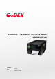
EZ2000PLUS / EZ6000PLUS BARCODE PRINTER USER MANUAL USER MANUAL VERSION ISSUE DATE P/N : EZ2000+/ EZ6000+ : Rev. D : 2013.07.
FCC COMPLIANCE STATEMENT FOR AMERICAN USERS This equipment has been tested and found to comply with the limits for a CLASS A digital device, pursuant to Part 15 of the FCC Rules. These limits are designed to provide reasonable protection against harmful interference when the equipment is operated in a commercial environment.
Safety instructions Please read the following instructions carefully. 1. Keep the equipment away from humidity. 2. Before you connect the equipment to the power outlet, please check the voltage of the power source. 3. Make sure the printer is off before plugging the power connector into the power jack. 4. It is recommended that you connect the printer to a surge protector to prevent possible transient overvoltage damage. 5. Be careful not to get liquid on the equipment to avoid electrical shock.
1. BARCODE PRINTER .................................................................. 1 1-1. Box content ............................................................................................. 1 1-2. Specifications .......................................................................................... 1 1-3. Interfaces Parallel port........................................................................... 5 1-4. Getting to know your printer .........................................................
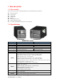
1. Barcode printer 1-1. Box content Please check that all of the following items are included with your printer: Barcode printer Power cord USB cable Label stock Ribbon Empty ribbon core Quick reference guide CD (with QLabel label software / user manual) 1-2.
Bitmap fonts: 6, 8, 10, 12, 14, 18, 24, 30, 16X26 and OCR A & B Bitmap fonts 90°, 180°, 270° rotatable, single characters 90°, 180°, 270° Resident Fonts rotatable Bitmap fonts 8 times expandable in horizontal and vertical directions Scalable fonts 90°, 180°, 270° rotatable Bitmap fonts 90°, 180°, 270° rotatable, single characters 90°, 180°, 270° rotatable Download Fonts Asian fonts 90°, 180°, 270° rotatable and 8 times expandable in horizontal and vertical directions Scalable fonts 90°, 180°, 270° rotatable
Model Print Method Resolution Print Speed Print Width EZ6200 Plus EZ6300 Plus Thermal Transfer / Direct Thermal 203 dpi (8 dot/mm) 300 dpi (12 dot/mm) 6 IPS (150 mm/s) 4 IPS (102 mm/s) 6.61” (168 mm) Min. 0.16” (4 mm)** Min. 0.16” (4 mm)** Print Length Max. 118” (3000 mm) Max.
1-D Bar codes: Code 39, Code 93, Code 128 (subset A, B, C), UCC/EAN-128 K-Mart, UCC/EAN-128, UPC A / E (add on 2 & 5), I 2 of 5, I 2 of 5 with Shipping Bearer Bars, EAN 8 / 13 (add on 2 & 5), Codabar, Post NET, EAN 128, DUN Barcodes 14, HIBC, MSI (1 Mod 10), Random Weight, Telepen, FIM, China Postal Code, RPS 128 and GS1 DataBar 2-D Bar codes: PDF417, Datamatrix code, MaxiCode, QR code and Micro QR code CODEPAGE 437, 850, 851, 852, 855, 857, 860, 861, 862, 863, 865, 866, 869, 737 Code Pages WINDOWS 1250, 12
1-3. Interfaces Parallel port Handshaking Interface cable Pinout Pin No.
USB port Connector type : Type B Pin No. 1 2 3 4 Function VBUS D- D+ GND PS/2 port Pin No. 1 2 3 4 5 6 Function DATA N/C GND VCC CLOCK N/C PS/2 computer-to-printer interface Printer Keyboard DATA 1 1 DATA N/C 2 2 N/C GND 3 3 GND VCC 4 4 VCC CLOCK 5 5 CLOCK N/C 6 6 N/C Internal interface UART1 wafer N.C TXD RXD CTS GND RTS E_MD RTS E_RST +5V GND +5V 1 2 3 4 5 6 7 8 9 10 11 12 1 2 3 4 5 6 7 8 9 10 11 12 Ethernet module N.
Applicator wafer +5V +24V Printing (out) Print error (out) Printed (out) Print (in) GND N.C GND N.
1-4. Getting to know your printer External view 4 1 3 2 1. 2. 3. 4. Operator panel with LCD display Lower cover plate Viewing window Printer cover 1 2 3 4 5 6 7 8 9 10 11 12 1. 2. 3. 4. 5. 6. 7. 8. 9. 10. 11. 12.
Internal view 12 11 1 2 10 3 4 9 5 6 8 7 1. 2. 3. 4. 5. 6. 7. 8. 9. 10. 11. 12. Ribbon rewind hub Ribbon supply hub Print mechanism Platen roller Tear-off plate Release lever for print head Adjustment wheel for sensor Paper guide Label tension guide Label supply hub Label roll guide Release catch 1 1.
2. Printer setup This printer supports the following printing methods: Thermal transfer Requires a ribbon for transferring a printed image to a medium. printing (TTP) Direct thermal Does not require a ribbon, only thermal paper. printing (DTP) Please check which printing method you are using and alter the settings accordingly in the printer driver, printer menu, and/or software. 2-1. Loading the label roll 1. Place the printer on a flat surface and open the printer cover. 2.
5. Place the label roll on the label supply hub, pushing it right up to the printer housing. (Do not apply too much pressure to avoid damaging the label stock.) 6. Fold the label roll guide back down and push it against the label roll. 【Note】 When moving the label roll guide, hold it only by the end that is attached to the bracket, not by its top. 7. Load the label roll into the printer as shown in the illustration. Pass it through the printer as indicated by the blue arrows. 8.
9. The labels pass between the wall of the printer housing and the adjustable paper guide. 【Note】 Pass the labels through the printer as shown in the illustration. 10. Return the print head release lever to its original position. 11. Then close the printer cover.
2-2. Loading the ribbon 1. Place the printer on a flat surface and open the printer cover. 2. Pull out the print head release lever as shown in the illustration (1) and turn it anticlockwise to a top right position (2). 1 2 3. Place a new ribbon on the ribbon supply hub. Then place an empty ribbon core on the ribbon rewind hub. 4. The two illustrations on the right show you how to install the ribbon depending on the ribbon type (ink side in or out). Ink side out 5.
2-3. Connecting the printer to the host computer 1. 2. 3. 4. Please make sure that the printer is switched off. Connect the power cord to the AC adapter and connect the adapter to the printer. Connect the USB cable to the printer and host computer. Switch on the printer. The operator panel should now light up.
2-4. Installing the driver 1. Insert the product CD in the CD/DVD drive of the host computer and open the "Windows Drivers" folder on the CD. 2. Select the icon for the driver file and click it to start the installation. 3. Follow the instructions on the screen. The Driver Wizard guides you through the installation procedure. 4. Select "Install printer drivers". 5. Specify your printer model.
6. Specify the port used to connect the printer to the host computer. 7. Enter a printer name and assign the appropriate rights. 8. Once the installation is complete, a summary of the printer settings is displayed. 9. Check whether the printer settings are correct and click "Finish" to start copying the driver files. 10. Wait until copying is complete, then finish the installation. 11. Once the driver installation is complete, the new printer should be visible in the "Printers and Faxes" folder.
3. Operator panel 3-1. Operator panel – introduction Function buttons FEED PAUSE CANCEL LED indicators POWER The POWER (Ready) LED lights up when the printer has started up and is ready to print. RIBBON Ribbon status indicator MEDIA Media status indicator 3-2. Function buttons – introduction FEED button When you press the FEED button, the printer moves the label to the defined stop position.
You can combine the FEED, PAUSE and CANCEL buttons in a number of ways to perform different printer functions: Function Self test Button Power 3 beeps Self test + Power 3 beeps 1 beep Now in Dump Mode 3 beeps Auto Sensing Mode 2x2 beeps Go to default 1 beep DL Mode Vx.xx keep the button pressed until you hear a beep. This mode is for download of the firmware only. Switch on the printer and 3 beeps Setting mode keep the button pressed for about 3-4 seconds, until you hear 3 beeps.
3-3. Settings mode In settings mode, you can change different settings, such as the printing mode, accessories / options, or media type. 1. 2. 3. Switch on the printer and make sure that the message "Ready" is shown on the display. Press the PAUSE button and keep it pressed for about 3-4 seconds until you hear 3 beeps and the message "Settings" is shown on the display. In settings mode, the buttons have the following functions: : Minus / Enter : Menu / Next : Plus / Exit 4.
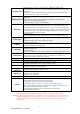
The following table lists descriptions of the available settings and options: Default: 10 Darkness Sets the temperature during printing. Values range from 0 to 19, the default setting is 10. Speed Sets the print speed (inches per second (ips)) Default: 12 Stop position The stop position determines how far the printed label is moved out (tear-off position / cut-off position) Default: 0 Adjusts the printer's stop position. Values range from 0 to Adjust stop position 10.
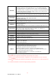
LCD language Code pages installed Keyboard layout Keyboard mode Buzzer No backfeed Password tag holes Reflective mode: For labels or normal paper with black marks on the reverse side.
Top of form USB / Ethernet Preview Lock setup password to access the settings. OFF Default: ON ON: Always starts printing at the top of the page. OFF Default: USB USB: Enables the USB port. Ethernet: Enables the Ethernet port. Lets you preview and check the settings. Locks the value(s) of any setting. When a value is locked, it cannot be altered by changes to the driver or by sending a command.
Settings mode diagram Items marked "*" are the default settings.
3-4. Self test The self-test function lets you check whether the printer is functioning normally. Here is how you run a self test: 1. 2. 3. Switch off the printer. Switch on the printer, keeping the FEED button pressed until you hear 3 beeps and the message "Self test" is shown on the display. After about one second, the printer will automatically print out the list below. That means the printer is functioning normally.
3-5. Dump mode If the label settings do not match the printer output, you should switch the printer to dump mode to check whether an error has occurred during the transfer between printer and host computer. In dump mode, the unprocessed raw data are sent to the printer and printed. This shows you quickly whether any data are sent to the printer at all. Here is how you switch to dump mode: 1. 2. 3. Switch off the printer. Switch on the printer, keeping the FEED button pressed.
3-7. Keyboard mode The printers of the EZ2000 Plus and EZ6000 Plus series support keyboards with a PS/2 interface, provided the parallel/PS/2 adapter is installed. Here is how you connect a PS/2 keyboard: 1. 2. Switch off the printer and plug the PS/2 connector into the appropriate printer port. Switch on the printer. The message "Keyboard mode [Y/N]" is shown on the display. Press the FEED button on the printer or the ENTER key on the keyboard to switch to keyboard mode.
5. Press "ENTER" to select a file. *Note: Press ↑or ↓to select the previous or next form in the list. 6. The input form for the serial number is now shown on the display. 7. Specify a start value (example: 00001). 8. The input form for the first variable is now shown on the display. 9. Specify a product name (example: Apple). 10. The input form for the second variable is now shown on the display. 11. Specify a random value (example: 199).
12. The input form for the print quantity is now shown on the display. 13. Specify a quantity (example: 3). 14. The printer will print three labels with the values for the two variables and the serial number specified.
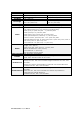
3-8. Error alerts In the event of a problem that prevents normal functioning of the printer, you will see an error message on the display and hear some beep signals. The LED indicators above the display will also light up. Fast flashing Error message displayed Slow flashing LED above the display RIBBON Light on Beeps Description Solution 4x2 beeps The print mechanism is not closed. Please make sure that the print mechanism is closed correctly.
Memory full File name not found File name already exists 30 EZ-2000+/6000+ User’s Manua 2x2 beeps The memory is full. 2x2 beeps Unable to find file. 2x2 beeps The file name already exists. Delete data you no longer need from the memory or use a CF card. Use the "~X4" command to print all file names and check whether the file exists in the memory. Change the name of the file and try storing it again.
3-9. WLAN Module Installation 1 2 3 4 5 6 7 8 9 10 1. Ethernet Cable 1.8M Secure Screw*2 Bracket Screw*2 Module Bracket WLAN module Module Connection Wire WLAN Antenna Nut (for Antenna) Washer (for Antenna) Antenna Bracket Make sure the power is off and the power cable is unplugged. Place the printer onto a smooth surface and open the top cover. 2. Remove the Left Top Cover from the printer. 3. Remove the covers of Ethernet port and Antenna port from the back plate of the printer. 4.
6. Connect the other end of Module Connection Wire to the main board. 7. Mount the WLAN module and secure it onto the back plate. 8. Thread Antenna Connection Wire through the hole on the Antenna Bracket. 9. Mount the Antenna Connection Wire and Antenna Bracket on the back plate and secure it with screws.
10. Put the Washer first and then tighten the Nut on the Antenna Connection Wire. 11. Turn the Antenna according to the direction as arrow showed to mount it on the Antenna Connection Wire. The angle of Antenna can be adjusted if needed. 12. Reassemble the Left Top Cover to complete the installation. Note 1: After the WLAN module installation is completed, please send the "^lan" printer command to printer for activating the Ethernet connection function.
4. Accessories 4-1. Internal rewinder (EZ2000 Plus) 1 Rewinder 2 Retention clip 3 Screws (set of 4) 4 Rewinder guide 【Note】 Maximum height of the rewound medium: 118 mm 1 2 3 【Suggestion】 Medium thickness: 0.06 mm–0.25 mm 1. 4 Place the printer on a flat surface and open the printer cover. 【Note】 Remember to switch off the printer before starting the installation. 2. Remove the cover for the rewinder module.
3. Remove the retention clip from the rewinder. 4. Secure the rewinder on the printer housing using the four screws supplied. 2 1 5. Now connect the rewinder cable to the printer housing. 6. Installation of the rewinder module is now complete.
4-2. Installing the rewinder guide (EZ2000 Plus) 1. Unscrew the screw marked in the illustration on the front of the printer, which secures the lower cover plate. 2. Remove the lower cover plate. 【Note】 Switch off the printer before starting the installation. 3. Mount the rewinder guide on the print mechanism and secure it with screws. 4. Installation of the rewinder guide is now complete. 5. Now load the label stock. 6. Pass the label stock through the rewinder from the bottom up.
4-3. Label dispenser (EZ2000 Plus) 1. Unscrew the screw marked in the illustration on the front of the printer, which secures the lower cover plate. 2. Remove the lower cover plate. 【Note】 Switch off the printer before starting the installation. 3. Place the printer the right way up again. 4. Pull out the print head release lever as shown in the illustration (1) and turn it anticlockwise to a top right position (2). 5. Remove the retention clip. 6. Now load the label roll into the printer.
8. Wind the label liner around the rewinder and secure it using the retention clip. 9. Return the print head release lever to its original position. 【Note】 Please make sure that the label stock rewinds the right way onto the rewind hub. 10. Replace the lower cover plate on the printer and secure it with screws 11. Press the lower part of the stripper sensor to fold it out. 12. The sensor locks in a horizontal position. 13. Close the printer cover to complete installation of the dispenser.
4-4. Internal rewinder for EZ6000 Plus 1 2 3 4 5 6 7 8 Motor Rewinder Rewinder connector bracket Retention clip Rewinder guide Cable tie Belt Screws (set of 10) 【Note】 For EZ-6200 Plus, the printing speed will be limited to 4 IPS when the rewinder or label dispenser is enabled. 1. Place the printer on a flat surface and open the printer cover. 2. 1 2 3 4 5 6 Remove the screws securing the left-hand part of the housing and the printer cover and remove these two parts of the housing.
7. Remove the two screws securing the connector bracket from the inside of the printer housing. 8. Now attach the rewinder connector bracket supplied. 9. Connect the rewinder connector bracket to the motherboard as shown in the illustration. 10. Remove the cover for the rewinder module. 11. Remove the retention clip from the rewinder. 12. Secure the rewinder on the printer housing using the four screws supplied.
14. Install the motor in the back section of the printer housing and align it with the 4 screw holes. 15. Do not tighten the screws fully, to leave room for installing the belt. 16. If required, adjust the position of the motor during installation of the belt. 17. Now tighten the screws securing the motor. 18. Gently pull the rewinder connection cables so they are fully inside the printer housing.
19. Connect the cable with the 5-pin connector to the jack marked "CUTTER" on the motherboard. 20. Connect the cable with the 4-pin connector to the jack marked "STRIP" on the motherboard. Connect the remaining connector to the motor. 21. Attach the motor cable and the "Rewinder full" cable to the motor bracket using the cable tie. 【Note】 You should position the "Rewinder full" cable underneath the belt to avoid possible faults. 22. Now replace the power supply unit and connect it to the motherboard.
27. Now load the label stock. 28. Pass the label stock through the rewinder from the bottom up. Secure the label stock on the rewinder using the retention clip. 【Note】 Make sure you choose the correct rewind direction. 29. Replace the printer cover to complete the installation. 【Note 1】 Before you start using the rewinder, please make sure that you have carried out all steps as shown in the illustrations. Then send the command "^XSET,REWINDER,1" to the printer to enable the rewind function.
4-5. Installing the label dispenser (EZ6000 Plus with rewinder) 1 2 3 Dispenser module Cable clips (set of 2) Screws (set of 2) 【Note】 For EZ-6200 Plus, the printing speed will be limited to 4 IPS when the rewinder or label dispenser is enabled. 1. Unscrew the screw marked in the illustration on the front of the printer, which secures the lower cover plate. 2. Remove the lower cover plate. 【Note】 Switch off the printer before starting the installation. 3.
5. Connect the dispenser cable connector to the rewinder jack. 6. Route the connection cable along the bottom of the printer housing using the cable clips. 7. Pull out the print head release lever and turn it anticlockwise to a top right position. 8. Using the lever shown in the illustration (1), fold out the dispenser module in the direction indicated by the arrow (2). 9. Strip a few labels off the label liner (approx. 400 mm) and pass the label liner through the dispenser module. 2 1 2 1 10.
11. Wind the label liner around the rewinder and secure it using the retention clip. 12. Return the print head release lever to its original position. 1 【Note】 2 The dispenser can only be used with labels of a minimum height of 20 mm. 【Suggestion】 When using the label dispenser, you should set the stop position to 25 mm. 13. Close the printer cover to complete installation of the dispenser.
4-6. Installing the cutter 1 Cutter cover (EZ2000 Plus) 2 Cutter cover (EZ6000 Plus) 3 Cutter module 4 Cable clips 5 Screws (set of 4) 【Note 1】 Remember to switch off the printer before installing the cutter. 【Note 2】 3 1 2 Do not use to cut adhesive labels! Glue residue will be left on the cutter blade and impair its functioning. The cutter has a blade life of 500,000 cuts when using paper weighing 160 g/m² and 250,000 cuts when using paper weighing 200 g/m². 1.
3. Secure the cutter module on the printer housing using the screws. 4. Connect the cutter cable connector to the cutter jack on the printer. 5. Route the connection cable along the bottom of the printer housing using the cable clips. 6. Place the cutter cover over the cutter module and secure it using the screw you removed from the lower cover plate. 7. Now load the label roll into the printer and close the printer cover.
4-7. Installing the parallel / PS/2 adapter 1 2 3 4 Parallel cable Parallel / PS/2 adapter Connection cable Screws (set of 2) 1 2 3 1. Check whether the printer is switched off. Place the printer on a flat surface and open the printer cover. 2. Unscrew the two screws marked in the illustration on the right and remove the left-hand side of the printer housing. 3. Unscrew the screws on the parallel port cover and remove the cover.
4. Install the parallel/PS/2 adapter in its place and secure it on the housing with screws. 5. Connect the 30-pin connection cable to the motherboard. 6. Replace the left-hand part of the printer housing and secure it with the screws you removed earlier. 7. Installation of the parallel/PS/2 adapter is now complete.
4-8. Installing the applicator interface 1 2 Applicator interface Screws (set of 2) 1 2 1. Place the printer on a flat surface and open the printer cover. 【Note】 Remember to switch off the printer before starting the installation. 2. Unscrew the two screws marked in the illustration on the right and remove the left-hand side of the printer housing. 3. Unscrew the screws on the applicator interface cover and remove the cover.
4. Pass the applicator cable through the opening into the housing. 5. Connect the applicator cable to the jack marked "APP" on the motherboard. 6. Secure the applicator interface using two screws. 7. Replace the left-hand part of the printer housing and secure it with the screws you removed earlier to complete the installation.
4-9. Installing the WLAN module – EZ2000 Plus / EZ6000 Plus 1 2 3 4 5 6 7 8 9 10 2. Ethernet cable, 1.8 m Fastening screws (set of 2) Screws for Ethernet module (set of 2) Bracket WLAN module Connection cable (module to motherboard) WLAN antenna Nut Washer Antenna bracket Make sure that the printer is switched off and the power cord disconnected from the printer. Place the printer on a clean flat surface and open the printer cover. 13. Remove the left-hand part of the printer housing. 14.
17. Plug the other end of the connection cable into the motherboard socket. 18. Secure the module bracket on the inside of the printer housing at the back. 19. Push the antenna connector through the antenna bracket. 20. Attach the antenna bracket to the back of the printer.
21. Put the washer on the antenna connector and secure the connector on the antenna bracket using the nut. 22. Screw the antenna onto the antenna connector. You can now adjust the angle of the antenna as required. 23. Replace the left-hand part of the printer housing to complete the installation. 【Note 1】 Once you have finished installing the Ethernet module, the command "^XSET,USBETHERNET,1" must be sent to the printer to enable the Ethernet module.
5. Maintenance and adjustment 5-1. Installing / removing the print head module 1. Open the printer cover. 【Note】 Remember to switch off the printer before removing the print head module. 2. Pull out the print head release lever as shown in the illustration (1) and turn it anticlockwise to a top right position (2). 1 2 3. Hold the print head module at the front and gently pull it out. 4. If you cannot remove the module by gently pulling it, use a screwdriver as shown in the illustration. 5.
5-2. Adjusting the print line Please contact your local dealer for technical support. 1. Open the printer cover. 2. Pull out the print head release lever as shown in the illustration (1) and turn it anticlockwise to a top right position (2). 1 2 3. TPH print line adjustment: When printing is slow or when printing on thick label stock, the print line must be moved to the front (in paper feed direction) for a better print result.
5-3. Adjusting the ribbon tension You can adjust the ribbon tension by turning the ribbon shaft knob (green wheel at the base of the ribbon supply hub – see illustration) clockwise or anticlockwise. There are 4 possible settings, which are marked on the knob of the ribbon rewind hub and the ribbon supply hub. When set to 1, the tension is highest, while the tension is lowest at 4.
5-4. Cleaning the thermal print head Dirt on the print head or ribbon may result in inadequate print quality (no printed image on part of the label). The printer cover should therefore be kept closed whenever possible. Keeping dirt and dust away from the paper or labels ensures a good print quality and a longer lifespan of the print head. Here is how you clean the print head: 1. 2. 3. 4. 5. Switch off the printer. Open the printer cover. Remove the ribbon.
5-5. Adjusting the balance and print head tension 1. Open the printer side cover. 2. Pull out the print head release lever as shown in the illustration (1) and turn it anticlockwise to a top right position (2). 1 2 When using a variety of label stock and ribbons, the ink may not be evenly distributed. If there is no printed image on one side of the paper, or the ribbon wrinkles, the print head pressure must be readjusted using the TPH spring boxes. 3.
5-6. Ribbon shield settings 1. The use of different ribbon materials may cause wrinkling of the ribbon, which in turn affects the print result as illustrated by the examples in (a) and (b). To change the print quality, you can adjust the ribbon shield screws. If your print result looks like the example in (a), you need to turn ribbon shield screw A clockwise. If your print result looks like the example in (b), you need to turn ribbon shield screw B clockwise. (a) 2.
5-7. Cutter settings 1. Socket head screws for adjusting the cutter are located on both sides of the cutter. 2. In the event of a paper jam, the cutter will no longer function correctly. Switch off the printer and use a hex key (#M3) to turn the socket head screw. 3. Turn the key anticlockwise to remove the jammed paper. 4. When you have removed the jammed paper, you can switch the printer back on. The cutter will automatically reset.
5-9. Troubleshooting Problem The printer is switched on but the display does not light up. One or both LEDs light up red and printing is interrupted. The label stock passes through the printer but no image is printed. The label stock jams during printing. Solution Check the power supply. Check the software settings (driver settings) or command codes. Look for the error alert in the table in Section 3-8. Error alerts.