EZPi1000 series BARCODE PRINTER USER MANUAL USER MANUAL VERSION ISSUE DATE P/N : EZPi1000 series : Rev. E : 2013.07.
FCC COMPLIANCE STATEMENT FOR AMERICAN USERS This equipment has been tested and found to comply with the limits for a CLASS A digital device, pursuant to Part 15 of the FCC Rules. These limits are designed to provide reasonable protection against harmful interference when the equipment is operated in a commercial environment.
Safety instructions Please read the following instructions carefully. 1. Keep the equipment away from humidity. 2. Before you connect the equipment to the power outlet, please check the voltage of the power source. 3. Make sure the printer is off before plugging the power connector into the power jack. 4. It is recommended that you connect the printer to a surge protector to prevent possible transient overvoltage damage. 5. Be careful not to get liquid on the equipment to avoid electrical shock.
1. BARCODE PRINTER .................................................................. 1 1-1. Box content ............................................................................................. 1 1-2. Specifications .......................................................................................... 1 1-3. Interfaces ................................................................................................. 3 1-4. Getting to know your printer ................................................
1. Barcode printer 1-1. Box content Please check that all of the following items are included with your printer: Barcode printer Power cord AC adapter USB cable Parallel cable (Centronics) Label stock Ribbon Ribbon hubs (set of 2) Empty ribbon core Label supply hub Label guide plates (set of 2) Quick reference guide CD (with QLabel label software / user manual) 1-2.
1-D Bar codes: Code 39, Code 93, Code 128 (subset A, B, C), UCC/EAN-128 K-Mart, UCC/EAN-128, UPC A / E (add on 2 & 5), I 2 of 5, I 2 of 5 with Shipping Bearer Bars, EAN 8 / 13 (add on 2 & 5), Codabar, Post NET, EAN 128, DUN Barcodes 14, HIBC, MSI (1 Mod 10), Random Weight, Telepen, FIM, China Postal Code, RPS 128 and GS1 DataBar 2-D Bar codes: PDF417, Datamatrix code, MaxiCode, QR code and Micro QR code CODEPAGE 437, 850, 851, 852, 855, 857, 860, 861, 862, 863, 865, 866, 869, 737 Code Pages WINDOWS 1250, 12
1-3. Interfaces Parallel port Handshaking Interface cable Pinout Pin No.
Internal interface UART1 wafer N.C TXD RXD CTS GND RTS E_MD RTS E_RST +5V GND +5V 1 2 3 4 5 6 7 8 9 10 11 12 1 2 3 4 5 6 7 8 9 10 11 12 Ethernet module N.
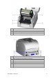
1-4. Getting to know your printer 1. 2. 3. 4. 5. 6. 7. Release buttons for opening the printer cover Printer cover Label supply hub Ribbon feed mechanism LCD module cover Print mechanism Front cover 1. 2. 3. 4.
1. 2. 3. 4. 5. Ribbon supply hub Label guides Paper feed roller Screw for adjusting the print line Label sensor (movable) 1. 2. 3. 4. 5. 6. 7. 8. 9.
2. Printer setup This printer supports the following printing methods: Thermal transfer Requires a ribbon for transferring a printed image to a medium. printing (TTP) Direct thermal Does not require a ribbon, only thermal paper. printing (DTP) Please check which printing method you are using and alter the settings accordingly in the printer driver, printer menu, and/or software. 2-1. Loading the ribbon 1. Place the printer on a flat surface.
5. Pass the ribbon under the print head. 6. Wind the ribbon onto the rewind core, attaching it with the adhesive strip at the end of the ribbon. Wind the ribbon 2-3 times around the core. 7. Close the print mechanism, making sure that it clicks into place.
2-2. Loading the label roll 1. Open the printer cover. 2. Place the label roll on the label supply hub. 3. Attach the guide plates to the label roll holder. 4. Now load the label roll into the printer. 5. Release the print mechanism and lift it. 6. Pass the labels through the paper guides up to the tear-off plate. 7. Adjust the paper guides to the label width. 8. Close the print mechanism.
2-3. Installing the label supply hub (A) Installing the label supply hub for 1" cores (B) Installing the label supply hub for 1.
2-4. Preparing for tag printing In tag printing, the tag hole indicates the height of a label. During adjustment, the sensor must therefore be positioned directly below the tag hole as shown in the illustration. The tag hole should be at least 3 mm in diameter to ensure correct functioning. Sensor position Sensor 2-5. Connecting the printer to the host computer 1. 2. 3. 4. Please make sure that the printer is switched off. Connect the power cord to the AC adapter and connect the adapter to the printer.
2-6. Installing the driver 1. Insert the product CD in the CD/DVD drive of the host computer and open the "Windows Drivers" folder on the CD. 2. Select the icon for the driver file and click it to start the installation. 3. Follow the instructions on the screen. The Driver Wizard guides you through the installation procedure. 4. Select "Install printer drivers". 5. Specify your printer model.
6. Specify the port used to connect the printer to the host computer. 7. Enter a printer name and assign the appropriate rights. 8. Once the installation is complete, a summary of the printer settings is displayed. 9. Check whether the printer settings are correct and click "Finish" to start copying the driver files. 10. Wait until copying is complete, then finish the installation. 11. Once the driver installation is complete, the new printer should appear in the "Printers and Faxes" folder.
3. Operator panel 3-1. Operator panel – introduction Function buttons FEED PAUSE CANCEL LED indicators POWER The POWER (Ready) LED lights up when the printer has started up and is ready to print. RIBBON Ribbon status indicator MEDIA Media status indicator 3-2. Function buttons FEED button When you press the FEED button, the printer moves the label to the defined stop position. If you are using continuous labels, pressing the FEED button will move label stock until you release the button again.
You can combine the FEED, PAUSE and CANCEL buttons in a number of ways to perform different printer functions: Function Self test Button Power 3 beeps Self test + Power 3 beeps 1 beep Now in Dump Mode 3 beeps Auto Sensing Mode 2x2 beeps Go to default 1 beep DL Mode Vx.xx keep the button pressed until you hear a beep. This mode is for download of the firmware only. Switch on the printer and 3 beeps Setting mode keep the button pressed for about 3-4 seconds, until you hear 3 beeps.
3-3. Settings mode In settings mode, you can change different settings, such as the printing mode, accessories / options, or media type. 1. 2. 3. Switch on the printer and make sure that the message "Ready" is shown on the display. Press the PAUSE button and keep it pressed for about 3-4 seconds until you hear 3 beeps and the message "Settings" is shown on the display. In settings mode, the buttons have the following functions: : Minus / Enter : Menu / Next : Plus / Exit 4.
The following table lists descriptions of the available settings and options: Default: 10 Darkness Sets the temperature during printing. Values range from 0 to 19, the default setting is 10. Speed Sets the print speed (inches per second (ips)) Default: 12 Stop position The stop position determines how far the printed label is moved out (tear-off position / cut-off position) Default: 0 Adjusts the printer's stop position. Values range from 0 to Adjust stop position 10.
LCD language Code pages installed Keyboard layout Keyboard mode Buzzer No backfeed Password EZPi1000 User Manual tag holes Reflective mode: For labels or normal paper with black marks on the reverse side.
Top of form USB / Ethernet Preview Lock setup password to access the settings. OFF Default: ON ON: Always starts printing at the top of the page. OFF Default: USB USB: Enables the USB port. Ethernet: Enables the Ethernet port. Lets you preview and check the settings. Locks the value(s) of any setting. When a value is locked, it cannot be altered by changes to the driver or by sending a command.
Settings mode diagram Items marked "*" are the default settings.
3-4. Self test The self-test function lets you check whether the printer is functioning normally. Here is how you run a self test: 1. 2. 3. Switch off the printer. Switch on the printer, keeping the FEED button pressed until you hear 3 beeps and the message "Self test" is shown on the display. After about one second, the printer will automatically print out the list below. That means the printer is functioning normally. * The contents of Self test label may vary depend on the setting of printer.
3-5. Dump mode If the label settings do not match the printer output, you should switch the printer to dump mode to check whether an error has occurred during the transfer between printer and host computer. In dump mode, the unprocessed raw data are sent to the printer and printed. This shows you quickly whether any data are sent to the printer at all. Here is how you switch to dump mode: 1. 2. 3. 4. Switch off the printer. Switch on the printer, keeping the FEED button pressed.
3-7. Keyboard mode The printers of the EZPi1000 series support keyboards with a PS/2 interface. Here is how you connect a PS/2 keyboard: 1. 2. Switch off the printer and plug the PS/2 connector into the appropriate printer port. Switch on the printer. The message "Keyboard mode [Y/N]" is shown on the display. Press the FEED button on the printer or the ENTER key on the keyboard to switch to keyboard mode.
5. Press "ENTER" to select a file. *Note: Press ↑or ↓to select the previous or next form in the list. 6. The input form for the serial number is now shown on the display. 7. Specify a start value 00001). 8. The input form for the first variable is now shown on the display. 9. Specify a product name (example: Apple). (example: 10. The input form for the second variable is now shown on the display. 11. Specify a random value (example: 199).
12. The input form for the print quantity is now shown on the display. 13. Specify a quantity (example: 3). 14. The printer will print three labels with the values for the two variables and the serial number specified.
3-8. Error alerts In the event of a problem that prevents normal functioning of the printer, you will see an error message on the display and hear some beep signals. The LED indicators above the display will also light up. Fast flashing Error message displayed Slow flashing LED above the display RIBBO MEDIA N Print head is open Both LEDs light up Entering cooling process Both flashing Light on Beeps Description Solution 4x2 beeps The print mechanism is not closed.
File name already exists EZPi1000 User Manual 2x2 beeps The file name already exists. the file exists in the memory. Change the name of the file and try storing it again.
4. Accessories 4-1. Installing the label dispenser 1 Dispenser module 2 Screws (set of 2) 【Note 1】 Remember to switch off the printer before installing the label dispenser. 【Note 2】 A label liner thickness of 0.006 mm ± 10% and a weight of 65 g/m2 ± 6% are recommended. 【Note 3】 The label dispenser will take labels up to a max. width of 110 mm. 【Tip】When using the label dispenser, set the stop position to 9 mm. 1. Open the printer cover by pressing the release buttons on both sides of the printer housing.
5. Connect the dispenser cable to the lower jack as shown in the illustration on the right. 【Important】The printer must be switched off, or the motherboard may be destroyed! There are 2 jacks: the lower jack is for the dispenser, the upper jack for the cutter. 6. Install the dispenser by pressing down first its left-hand side and then its right-hand side. 7. Secure the dispenser using the screws provided for this purpose. 8. Pass the paper through the guides.
10. Pass the label stock through the printer as shown in the illustration on the right. 11. Close the print mechanism and the label dispenser. 12. Press the FEED button to set the label position and complete the installation.
4-2. Installing the cutter 1 Cutter module Tap screws 2 (3x8 – set of 2) 【Note 1】 Remember to switch off the printer before installing the cutter. 【Note 2】 Do not use to cut adhesive labels! Glue residue will be left on the cutter blade and impair its functioning. The cutter has a blade life of 500,000 cuts when using paper weighing 160 g/m², and of 250,000 cuts when using paper weighing 200 g/m². 1. Open the printer cover by pressing the release buttons on both sides of the printer housing. 2.
jack is for the dispenser, the upper jack for the cutter. 6. Install the cutter by pressing down first its left-hand side and then its right-hand side. 7. Fold out the cutter as shown in the illustration. 8. Secure the cutter using the screws provided for this purpose. 9. Once you have secured the cutter with the screws, fold it back in again. 10. Pass the labels through the guides. 11. Close the mechanism. print 【Note】 We advise against using inside wound label stock.
12. To finish, press the FEED button to set the label position. 【Note】 Labels should be at least 20 mm high. When using the printer with the cutter, you should set the stop position (^E) to 30.
4-3. Installing the WLAN module 1 2 3 4 5 6 7 8 9 10 11 12 1. Ethernet cable, 1.8 m Fastening screw Screws for Ethernet module (set of 2) Bracket WLAN module Connection cable (module to motherboard) WLAN antenna Nut Washer Fixing plate Antenna bracket SPRING LEAF 接地彈片 Make sure that the printer is switched off and the power cord disconnected from the printer. You should work on a clean, flat surface. Turn the printer upside down and remove the two screws marked in the illustration from the printer housing.
5. Unscrew the fastening screw on the Ethernet module. 6. Remove the Ethernet module and its connection cable. 7. Unscrew the nut on the PS/2 port using a spanner. Unscrew the earthing screw and disconnect the cable from the PS/2 port to remove the PS/2 port. Now tighten the earthing screw again. 8. Attach the WLAN module to the bracket. 9. Remove the cable tie from the connection cable and extend the cable to its full length. Now plug the cable connector into the Ethernet module socket.
10. Secure the module on the printer housing and plug the other end of the connection cable into the socket on the motherboard. 11. Pass the connection cable underneath the other connection cables as shown in the illustration. 【Caution】Please make sure that you position all cables in such a way that they are not damaged when you reassemble the printer. 12. Put the antenna connector through the antenna bracket and then through the opening for the antenna jack as shown.
13. Put first the fixing plate and then the washer on the antenna connector. Now secure them with the nut. 14. Screw the antenna onto the antenna connector. You can now adjust the angle of the antenna as required. 15. Finally, replace the top part of the printer housing and secure it on the underside of the printer using the screws you removed earlier.
4-4. Installing the CF card adapter 1 CF card adapter (front) CF card adapter 2 (back) 【Note】 Remember to switch off the printer before installing the CF card adapter. 1. Open the printer cover by pressing the release buttons on both sides of the printer housing. 2. Remove the label supply hub. 3. Open and remove the plastic cover inside the printer. 1 2 4. Align the sockets and pins on the CF card adapter carefully with those on the motherboard before connecting the adapter.
4-5. Instructions for using the CF card Once the CF card adapter is installed, all EZPi1000 Plus series printers will recognise the CF card. If the printer's internal memory is not sufficient to store label formats, graphics or fonts, you can use the CF card as an external memory to increase the storage capacity. Please follow these instructions when using the CF card: 1. 2. 3. 4. 5. 6. Remember to switch off the printer before installing the CF card or removing it from the card slot.
5. Maintenance and adjustment 5-1. Cleaning the print head Dirt on the print head or ribbon, or glue residue from the label stock may result in inadequate print quality. The printer cover must therefore always be closed during printing. Keeping dirt and dust away from the paper or labels ensures a good print quality and a longer lifespan of the print head. Here is how you clean the print head: 1. 2. 3. 4. 5. Switch off the printer. Open the printer cover. Release the print mechanism and lift it.
5-3. Adjusting the print line When the print line is incorrectly set, the print quality on one side of the medium may suffer. In such a case, the print line must be adjusted so it is positioned parallel to the paper feed roller. 1. 2. To move the print head in direction A as indicated by the blue arrow, turn the adjustment wheel anticlockwise (see arrow 1). A 1 B 2 To move the print head in direction B as indicated by the blue arrow, turn the adjustment wheel clockwise (see arrow 2). 5-4.
5-5. Troubleshooting Problem The printer is switched on Solution Check the power supply. Check the software settings (driver settings) or but the display does not light up. One or both LEDs light up red and printing is interrupted. command codes. Look for the error alert in the table in Section 3-8. Error alerts. Check whether the cutter is functioning normally and whether it is cutting at all. (Only if a cutter is installed.