RT200i/RT230i BARCODE PRINTER USER MANUAL User Manual : RT200i series Version : Rev. 1.6 Issue Date : 2013.07.
RT200i/RT230i USER MANUAL CONTENTS 1 Barcode Printer 001 1.1 Box Content 001 1.2 Getting to Know Your Printer 002 2 Printer Setup 005 2.1 Open the Printer 005 2.2 Loading the Ribbon 006 2.3 Loading the Label Roll Module 010 2.4 Connecting the Printer to the Host Computer 013 2.5 Installing Printer Driver and QLabel with Super 015 Wizard CD 3 Setting and Control for Operation Panel 020 3.1 Operation Panel 020 3.2 LCD Interface Introduction 021 3.
RT200i/RT230i USER MANUAL FCC COMPLIANCE STATEMENT FOR AMERICAN USERS This equipment has been tested and found to comply with the limits for a CLASS A digital device, pursuant to Part 15 of the FCC Rules. These limits are designed to provide reasonable protection against harmful interference when the equipment is operated in a commercial environment.
RT200i/RT230i USER MANUAL SAFETY INSTRUCTIONS Please read the following instructions carefully. 1. Keep the equipment away from humidity. 2. Before you connect the equipment to the power outlet, please check the voltage of the power source. 3. Make sure the printer is off before plugging the power connector into the power jack. 4. It is recommended that you connect the printer to a surge protector to prevent possible transient overvoltage damage. 5.
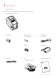
1 Barcode Printer 1.1 Box Content Please check that all of the following items are included with your printer. RT200i/RT230i Barcode Printer Label Stock USB Cable Ribbon Module Power Adapter Empty Ribbon Core Power Cord Ribbon AC Adapter CD RT200i/RT230i Quick Guide Including GoLabel software and RT200i/RT230i user manual. RT200i RT200/ Series * Package content may vary per region.
1 Barcode Printer 1.
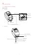
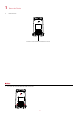
1 Barcode Printer Bottom View COVER OF THE MODULE CONNECTION JACKS **** Cut-outs are not intended for wall-mount use.
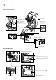
1 Barcode Printer The Internal View of Printer LABEL SUPPLY MODULE PAPER PRESS BAR TOP COVER LABEL SUPPLY HUB RELEASE CATCH RELEASE CATCH Release catch for closing the printer cover Release catch for opening the label supply hub LABEL SENSOR MODULE LABEL GUIDES PLATEN MODULE LABEL SENSOR GUIDE TRACK PLATEN PLATEN LOCKERS The Printing Mechanism RIBBON REWIND MECHANISM RIBBON REWIND WHEEL HOLDER OF RIBBON REWIND CORE RIBBON SUPPLY MECHANISM HOLDER OF RIBBON SUPPLY CORE RIBBON SUPPLY WHEEL
2 Printer Setup 2.1 Open the Printer Open the Printer Cover and the Printing Mechanism Place the printer on a flat surface. Open the printer cover by pulling the release catches on both sides of the printer and lift the cover.
2 Printer Setup 2.2 Loading the Ribbon A New Ribbon Module Installation A NEW RIBBON 1. EMPTY RIBBON CORE Attach the ribbon to the empty ribbon core with the adhesive strip at the end of the ribbon. Notch on left side Stick on empty ribbon core 2. Wind the ribbon around the empty ribbon core for 2 to 3 circles. Wind the ribbon around the core 3. A ribbon module is assembled as below.
2 Printer Setup Load the Ribbon on the Printer For Ribbon Supply Module RIBBON SUPPLY MODULE 1. Place the right-hand side of ribbon first. Push the ribbon to tighten the spring of the holder Right side SPRING OF HOLDER Align the ribbon core to the holder 2. Then place the left-hand side of the ribbon.
2 3. Printer Setup The ribbon supply module loading is completed. Load the Ribbon on the Printer For Ribbon Rewind Module RIBBON REWIND MODULE 1. Pass the ribbon to round the print head.
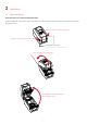
2 2. Printer Setup Place the right-hand side of empty ribbon core first. Right side Align the empty ribbon core to the holder Push the empty ribbon core to tighten the spring of the holder SPRING OF HOLDER 3. Then place the left-hand side of the empty ribbon core. Turn the ribbon wheel to align the notch of empty ribbon core to the spoke. Left side Rotate backward Align the notch of empty ribbon core to the spoke NOTCH OF RIBBON CORE SPOKE 4.
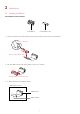
2 Printer Setup 2.3 Loading the Label Roll Module A New Label Supply Module Loading LABEL STOCK LABEL SUPPLY HUB 1. Unlock the release catch to lift the label supply hub. 1 Push rightward 2 Lift the label supply hub upward 2. Place the label stock on the label supply hub.
2 3. Printer Setup Push the label supply module downward and close the release catch. Push downward to fix the module 4. A new label supply module is completed. Loading the Label Roll Module on the Printer 1. Feed the Label through the label guides and adjust the label guides to the label width. The label guides will help to prevent the label swaying.
2 2. Printer Setup Unlock the release catch to close the printer cover. 2 1 Close the printer cover 3. Push the release catch Press the FEED key and make sure the label is fed smoothly. The label loading is completed now. **** Please keeps the rack gear clean to ensure the smoothness of label holder.
2 Printer Setup 2.4 Connecting the Printer to the Host Computer 1. Please make sure that the printer is switched off. 2. Connect the power cord to the AC adapter. POWER CORD AC ADAPTER Connect the jack of the power adapter to the printer and connect the plug of the power adapter to the socket of the wall.
2 3. Printer Setup Connect the USB/serial cable to the printer and host computer. RT200i/RT230i BARCODE PRINTER USB PORT USB CABLE PLUG PLUG PC 4. Pressing the POWER button. The LCD screen should now lights up.
2 Printer Setup 2.5 Installing Printer Driver and GoLabel with Super Wizard CD 1. Insert the Super Wizard CD in the CD/DVD drive of the host computer and the program should pop up automatically. You will see the Welcome screen first. On the Welcome screen, choose “Standard Installation”. 2. The wizard will then ask you to make sure your USB and power cables are connected and that the power is turned on. Make sure that is done and then click “Next”. 3.
2 Printer Setup 4. As the printer driver and GoLabel are installing, a screen will display a progress bar. 5. Once the installation is complete, you can start to make and print labels with GoLabel or throug the printer driver. 6. As the optional steps, you can also print a test label or register your printer during the “Standard Installation” procedure. ****If you need more resources, tools or reference documents, you can also find them on Super Wizard CD.
2 Printer Setup Installing Printer Driver Directly From CD Folder 1. Insert the product CD in the CD/DVD drive of the host computer and open the "Seagull Drivers" folder on the CD. Select the icon for the driver file and click it to start the installation. 2. Follow the instructions on the screen. The Driver Wizard guides you through the installation procedure. Select "Install printer drivers". 3. Specify your printer model.
2 Printer Setup 4. Specify the port used to connect the printer to the host computer. 5. Enter a printer name and assign the appropriate rights. Godex RT200i Godex RT200i 6. Once the installation is complete, a summary of the printer settings is displayed. Check whether the printer settings are correct and click "Finish" to start copying the driver files. Wait until copying is complete, then finish the installation.
2 7. Printer Setup Once the driver installation is complete, the new printer should appear in the "Printers and Faxes" folder.
3 Setting and Control for Operation Panel 3.1 Operation Panel Operation Panel Introduction OPERATION PANEL LCD SCREEN POWER BUTTON FEED BUTTON DIRECTION KEY POWER Button Press the POWER button to turn on the printer, and the START UP SCREEN appears. The printer is on “ready to print” status, the LCD screen should display the message “READY“ on the screen. When printer is turned on, keep pressing the POWER button for 3 second will turn the printer off.
3 Setting and Control for Operation Panel 3.2 LCD Interface Introduction Getting Started Press the POWER button to turn on the printer, and the START UP SCREEN appears. Power on If the printer is on “ready to print” status, the LCD screen should display the message “Ready“ on the screen. Please keep pressing button and wait for the timer to be filled, then the LCD interface will enter into the MAIN PAGE for SETTING MODE. You can make various setting functions in SETTING MODE.
3 Setting and Control for Operation Panel Operations on Setting Page On MAIN PAGE, press or button to move the cursor and select the functions. Select a designated function and press FEED button, you will enter the SETTING PAGES for the function. Select or Enter On SETTING PAGES, press or button to select the setting items. Select a designated function and press FEED button, you will enter the SETTING VALUE PAGES for the function.
3 Setting and Control for Operation Panel On SETTING VALUE PAGES, press or button to change the setting values. Select or Press FEED button will apply the setting value you just selected, and the red tick will appear to mark the value. Apply **** The blue arrow indicates the value you are selected. **** The red tick indicates that the selected value is applied now.
3 Setting and Control for Operation Panel Exit from Current Page to Ready Status The icon on top-left corner displays the capture of upper level screen and also guides you back to upper level with left or up arrow. NAVIGATION ICON On SETTING VALUE PAGES, press button will go back to the upper level screen. Back to the Setting page On SETTING PAGES, press button will go back to the MAIN PAGE screen.
3 Setting and Control for Operation Panel On MAIN PAGE, select the “EXIT” icon and press the FEED button to exit from SETTING MODE and the printer goes back to READY status.
3 Setting and Control for Operation Panel 3.3 LAN Setting Operations on Setting Page On MAIN PAGE,press or button to move the cursor and select the functions. Select a designated function and press FEED button, you will enter the SETTING PAGES for the function. Select Device or Device Enter LAN Setting On LAN Setting PAGE,press or button to select the setting items.
3 Setting and Control for Operation Panel The default of DHCP is Disable. ,Press or button to change the setting values. Select to enable DHCP Press FEED button twice to save the setting. Press FEED once to exit. Press FEED again to save and return to previous SETTING PAGE.
3 Setting and Control for Operation Panel 3.4 LCD Password Operations on Setting Page On MAIN PAGE, press or button to move the cursor and select the functions. Seclect a designated function and press FEED button, you will enter the SETTING PAGE for the function. Select Device or Device Enter LCD Password The default of LCD Setting is Disable. Press or button to change the setting values.
3 Setting and Control for Operation Panel Select button again to setup the password Press FEED button twice to svae the setting Press FEED button onece to exit.
3 Setting and Control for Operation Panel 3.5 LCD Interface Function Main Page Printer Setting Setting items for printer, ex. Printing speed, darkness. Also includes a Printing Wizard for your ease of printing. Setting items for printing label, ex. Rotation, Printing position offset. Label Setting Option modules and connection port settings. Device Self-Diagnose functions for printer, ex. TPH testing, self-test page printing. Analysis Exit from Setting Mode.
3 Setting and Control for Operation Panel Setting Items in Setting Mode English German 繁體中文 简体中文 2-5 or 7 0-19 Label with Gaps Label with Marks Continuous Direct Thermal Thermat Transfer 0-40 0-19 2-5 or 7 LCD Language Printer Setting Speed Darkness Wizard Media Type Printer Mode Tear-off Position Darkness Speed Media Detection Sensor Media Type Direct Thermal Thermat Transfer 0-40 Apply Cancel 850 852 437 860 863 865 857 861 862 855 866 737 851 869 Win 1252 Win 1250 Win 1251 Win 1253 Win 1254 Win 12
3 Setting and Control for Operation Panel Buzzer Device Optional Setting LAN Setting LCD Password Serial Port Setting RTC Setting Apply Cancel None Cutter Option Label Dispensor Applicator Apply Pre-Printing Cancel 09100 Part NO. Disable DHCP Enable Default Gateway 192.168.000.254 192.168.102.076 Dynamic IP 255.255.255.
3 Setting and Control for Operation Panel Status of LCD Interface When printer is on standby status (ready to print), the LCD interface will display “Ready” on screen. You can only print on this “Ready“ status. If there is any printers error, the LCD screen will display the error screen to show the type of error. You can fix the error according the notice.
3 Setting and Control for Operation Panel 3.6 Label Calibration and Self Test Label Calibration The printer can automatically detect and store label height. That means the host computer does not need to transmit the label height to the printer. Self Test Self-test function lets you check whether the printer is functioning normally. Here is how you run the label size calibration and self test. 1. Check that the label stock is loaded correctly. 2. Turn off the printer. 3.
3 Setting and Control for Operation Panel Label Calibration Button A hardware button to make a Label Calibration while printer encountering ‘’Media Error’’ during the cases when first-time printer start up or change label or ribbon to another type, such as change using gap label to continuous or black mark labels. CALIBRATION BUTTON Press Press C-button for 2 seconds, it will make an auto-sensing to calibrate the label and ribbon’s parameters.
3 Setting and Control for Operation Panel 3.7 Error Alerts In the event of a problem that prevents normal functioning of the printer, you will see an error message on LCD screen and hear some beep signals. Please refer to below table for the error alerts. OPERATION PANEL LCD SCREEN FEED BUTTON POWER BUTTON Operation Panel Status DIRECTION KEY Type Beeps Print Head Error 2 x 4 beeps The printing mechanism is not correctly closed. Open the print mechanism and close it again.
3 Setting and Control for Operation Panel Operation Panel Status Type Beeps Description Solution The memory is full. The printer Delete unnecessary data or install prints the message "File System full additional memory. ". File Error Use the "~X4" command to print Unable to find file. The printer all files. Then check whether the 2 x 2 beeps prints the message "File Name not files exist and whether the names found" are correct. A file of the same name already exists.
3 Printer Setting and Control 3.8 USB Host Definition : USB Host port supports either device:USB memory stick, keyboard or scanner. Purpose USB memory stick : It extends the user memory space up to 32GB for Graphic, Font, Label Format, DBF and Command files downloading. The printer’s Firmware also can be updating if copy new version of Firmware into USB memory stick. Connecting an USB keyboard to printer for ‘’ Standalone’’ mode operation.
3 Printer Setting and Control USB Keyboard When plug-in an USB keyboard to the printer, LCD panel will display “Standalone Mode”, press the “Enter” key on keyboard and “Feed” key in the printer to entering to the dialog for “Recall Label” operation. Only the sub-dialog “Recall Label” is able operating by keyboard as follow definition: 1. Press “ESC” key to exist from “Standalone Mode” or back to previous dialog 2.
4 NetSetting for Ethernet 4.1 Installing the NetSetting software The NetSetting software is used to manage the network configurations when connecting the printer via Ethernet port. It is available on product CD or can be downloaded from official website. To install the NetSetting, please follow below steps. 1. Insert the product CD in the CD/DVD drive of the host computer and open the "Ethernet" folder on the CD. 2.
4 NetSetting for Ethernet 4.2 The Interface of NetSetting Click the NetSetting icon to start the program; you will see the start page as below. The start page will display the basic information of connected printer and your PC. RT200i Click the magnifier icon to search the Godex printers which are connected via Ethernet port in you network environment. Once a connected Godex printer is detected, it will be listed on the start page.
4 NetSetting for Ethernet IP Setting The IP Setting tab can change the printer name, Port number, Gateway setting and the password for configuring the printer. You can also set the printer’s IP address ether by DHCP or by Static IP. You can press “Set” button to apply the settings and “ReGet” button to refresh the setting values. **** To fully benefit from the NetSetting software, you should be familiar with basic networking principles.
4 NetSetting for Ethernet Alert Path Setting NetSetting will send the alert messages to designated mail account when the error happened on printer. The alert messages are sent by SMTP (Simple Mail Transfer Protocol) or SNMP (Simple Network Management Protocol). You can set or change the configurations of SMTP and SNMP on this “Alert Path Setting” tab. You can press “Set” button to apply the settings and “ReGet” button to refresh the setting values.
4 NetSetting for Ethernet Alert Message Setting For the alert message notification function, you can decide which error cases need to be sent out to the operator. Moreover, the alert messages can be set to be sent by SMTP, SNMP or both. You can press “Set” button to apply the settings and “ReGet” button to refresh the setting values.
4 NetSetting for Ethernet Printer Configuration Set or change the configurations of connected printer. Most of key settings for the printer operation can be done by this setting page. RT200i You can press “Set” button to apply the settings and “ReGet” button to refresh the setting values.
4 NetSetting for Ethernet User Command The “User Command” tab provides a communication interface for operator to control the printer. Input printer commands in "Input Command" window and press “Send Command” button, the commands will be sent to the printer. For some commands that will return response message, the message will be displayed in "Output Message" window. You can press “Send Command” button to send printer commands via Ethernet port and control the printer remotely.
4 NetSetting for Ethernet Firmware Download On “Firmware Download” tab, the current version of printer firmware will be showed on the screen. If you need to update the printer firmware, just specify the file location of firmware file and press “Start Download Firmware” button. The printer firmware then can be updated remotely. BOOT : 1.000a1 F/W : RT200i 1.
5 Accessories 5.1 Preparation Steps Before installing the optional modules, please make some preparations as follows. 1. Turn off the printer Remember to switch off the printer before installing any module. 2. Open the printer cover and the printing mechanism Open the printer cover by pulling the release catches on both sides of the printer and lift the cover. Please see the Section 2.1 for further information about Open The Printer. The printing mechanism is lifted up with the printer cover 3.
5 4. Accessories Remove the platen Lift up the release clips on both sides of the platen to release and pull upward the platen. Release the clip CLIP Pull up the platen 5. Ribbon loading Please see the Section 2.2 for further information about Loading The Ribbon. 6. Label loading Please see the Section 2.3 for further information about Loading The Label Roll Module.
5 Accessories 5.2 Installing the Label Dispenser The Overview of the Label Dispenser PAPER SENSOR PAPER FEED ROLLER CONNECTION CABLE OF LABEL DISPENSER COVER Preparation Steps Please see the Section 5.1 Preparation Steps to complete the preparation steps before installing the label dispenser. Installing the Label Dispenser 1. Pass the connection cable through the slot of the printer. **** A label liner thickness of 0.006 mm ± 10% and a weight of 65 g/m2 ± 6% are recommended.
5 Accessories 2. Place label dispenser to align both holes of screw and then tighten the screws. 3. Place the platen back to the printer and lock the clips. Lock the clip CLIP 4. Close the top cover and printing mechanism. 5. Turn the printer upside down.
5 6. Accessories Open the cover on the bottom of printer. COVER OF THE MODULE CONNECTION JACKS Open the cover 7. Plug the connector fo the label dispenser to the jack. Plug JACK CONNECTOR OF THE CONNECTION CABLE 8. Close the cover of the module connection jacks.
5 Accessories Loading Label Roll with the Label Dispenser Module 1. Remove the first label from the label stock. LABEL STOCK LABEL LINER Tear a label 2. THE FIRST LABEL Feed the Label stock through the label guides. Through the label guides 3. Pull the label liner through the platen and the steel of the label dispenser. LABEL LINER PLATEN STEEL ****Labels should be at least 25 mm high.
5 4. Accessories The feeding path of label and liner should be as shown in below graphic. LABEL LABEL LINER LABEL STOCK PLATEN ROLLER 5. Close the label dispenser and printer cover. The installation is completed now.
5 6. Accessories Press the FEED button to feed the label. The label will be peeled from the liner while it passes through the label dispenser. Press the FEED button LABEL LABEL LINER **** There is a paper sensor on the Label Dispenser module. It will stop the printing if it is covered by label. Remove the last printed label and the printer will then continue to print next label.
5 Accessories 5.3 Installing the Cutter The Overview of the Cutter CONNECTION CABLE OF CUTTER FEED-OUT SLOT COVER Preparation Steps Please see the Section 5.1 Preparation Steps to complete the preparation steps before installing the cutter. Installing the Cutter 1. Pass the connection cable through the slot of the printer. ****Remember to switch off the printer before installing the cutter.
5 Accessories 2. Place the cutter to align both holes of screw and then tighten the screws. 3. Place the platen back to the printer and lock the clips. Lock the clip CLIP 4. Close the top cover and printing mechanism. 5. Turn the printer upside down.
5 6. Accessories Open the cover on the bottom of printer. COVER OF THE MODULE CONNECTION JACKS Open the cover 7. Plug the connector for the cutter to the jack. Plug JACK CONNECTOR OF THE CONNECTION CABLE 8. Close the cover of the module connection jacks. COVER OF THE MODULE CONNECTION JACKS Close the cover ****The printer must be switched off, or the motherboard may be destroyed! ****There are 2 jacks : the lower jack for the label dispenser, the upper jack for the cutter.
5 Accessories Installing the Label Roll Module on the Printer 1. Pass the labels through the guides and the cutter. Through the label guides Through the cutter 2. Close the top cover and printing mechanism. To finish, press the FEED button to set the label position. Close the top cover Press the FEED button ****We advise against using inside wound label stock. ****Labels should be at least 30 mm high. When using the printer with the cutter, you should set the stop position (^E) to 30.
6 Maintenance and Adjustment 6.1 Cleaning the Print Head Dirt on the print head or ribbon, or glue residue from the label stock may result in inadequate print quality. The printer cover must therefore always be closed during printing. Keeping dirt and dust away from the paper or labels ensures a good print quality and a longer lifespan of the print head. Cleaning Steps Here is how you clean the print head. 1. Turn off the printer. 2. Open the printer cover. 3. Remove the ribbon. 4.
6 Maintenance and Adjustment 6.2 Troubleshooting Problem The printer is switched on but the LCD screen does not light up. The LCD screen show the notice icon and printing is interrupted. Solution ♦ Check the power supply. Please see the Section 2.4 ♦ Check the software settings (driver settings) or command codes. ♦ Look for the error alert in the table in Section 3.5. Error Alerts. ♦ Check whether the print mechanism is closed correctly. Please see the Section 3.
RT200i/RT230i USER MANUAL APPENDIX PRODUCT SPENIFICATIONS RT200i Model Print Method RT230i Thermal Transfer / Direct Thermal Resolution 203 dpi (8 dots/mm) 300 dpi (12 dots/mm) Print Speed 7 IPS (177 mm/s) 5 IPS (127 mm/s) Print Width 2.12” (54 mm) 2.24” (56.9 mm) Print Length Min. 0.16” (4 mm)** ; Max. 68” (1727 mm) Min. 0.16” (4 mm)** ; Max.
RT200i/RT230i USER MANUAL APPENDIX PRODUCT SPENIFICATIONS RT200i Model USB Device (B-Type) USB Device (B-Type) Serial port: RS-232 (DB-9) USB Device (B-Type) Interfaces USB Host (A-Type) RT230i Serial port: RS-232 (DB-9) USB Device (B-Type) Serial port: RS-232 (DB-9) USB Host (A-Type) Serial port:RS-232 (DB-9) IEEE 802.3 10/100Base-Tx USB Host (A-Type) IEEE 802.
RT200i/RT230i USER MANUAL APPENDIX INTERFACE Pinout Description USB Connector Type : Pin NO. Function 1 VBUS Type B 2 D- 3 D+ 4 GND Serial Port Default settings: Baud rate 9600, no parity, 8 data bits, 1 stop bit, XON/XOFF protocol and RTS/CTS RS232 Housing(9-pin to 9-pin) DB9 Socket 1 RXD 2 TXD 3 DTR 4 GND 5 DSR 6 RTS 7 CTS 8 RI 9 Computer 1 2 3 4 5 6 7 8 9 DB9 Plug +5V, max 500mA TXD RXD N/C GND RTS CTS RTS N/C Printer ****The total current to the serial port may not exceed 500mA.
RT200i/RT230i USER MANUAL APPENDIX FILE MANIPULATION WHEN USING USB STICK File Manipulation The files in both devices (USB memory stick and printer internal Flash memory) are able to copy and move by the commands ‘’~MCPY’’ and ‘’MMOV’’ that sends from GoLabel on a PC via either connection - USB or Ethernet ports. Copy Syntax ~MCPY,s:o.x,d:o.