RT860i BARCODE PRINTER USER MANUAL User Manual : RT860i Version : Rev. 1.0 Issue Date : 2014.07.
RT860i Series USER MANUAL CONTENTS 1 Barcode Printer 001 1.1 Box Content 001 1.2 Getting to Know Your Printer 002 2 Printer Setup 006 2.1 Open the Printer 006 2.2 Loading the Ribbon 007 2.3 Loading the Label Roll Module 012 2.4 Connecting the Printer to the Host Computer 014 2.5 Wizard CD Standard Installation 016 2.6 Wizard CD Other Choice Installation 019 3 Printer Setting and Control 022 3.1 Operation Panel 022 3.2 LCD Toucn Panel Introduction 023 3.
RT860i Series USER MANUAL FCC COMPLIANCE STATEMENT FOR AMERICAN USERS This equipment has been tested and found to comply with the limits for a CLASS A digital device, pursuant to Part 15 of the FCC Rules. These limits are designed to provide reasonable protection against harmful interference when the equipment is operated in a commercial environment.
RT860i USER MANUAL SAFETY INSTRUCTIONS Please read the following instructions carefully. 1. Keep the equipment away from humidity. 2. Before you connect the equipment to the power outlet, please check the voltage of the power source. 3. Make sure the printer is off before plugging the power connector into the power jack. 4. It is recommended that you connect the printer to a surge protector to prevent possible transient overvoltage damage. 5.
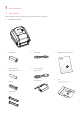
1 Barcode Printer 1.1 Box Content Please check that all of the following items are included with your printer. RT860i Barcode Printer Label Stock USB Cable RT860i Series Quick Guide RT860i Ribbon Module Empty Ribbon Core Ribbon Series Power Adapter Power Cord AC Adapter CD Including GoLabel software and user’s manual. Ribbon Hubs Set of 2.
1 Barcode Printer 1.
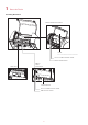
1 Barcode Printer Bottom View COVER OF THE MODULE CONNECTION JACKS **** Cut-outs are not intended for wall-mount use. Please make sure that the machine and personnel protective measures in case you need to use the wall-mount.
1 Barcode Printer The Internal View of Printer LABEL GUIDE PLATE Set of 2 LABEL SUPPLY HUB Set of 2 LABEL SUPPLY MODULE LABEL GUIDE Set of 2 RELEASE CATCH Release catch for opening RELEASE CATCH Release catch for closing the printer cover LABEL SENSOR MODULE LABEL SENSOR GUIDE TRACK PLATEN MODULE PLATEN PLATEN LOCKERS 4 the label supply hub
1 Barcode Printer The Printing Mechanism RIBBON REWIND MECHANISM COVER The cover for Ribbon rewind mechanism NOTCH OF RIBBON REWIND WHEEL RIBBON REWIND WHEEL PRINT HEAD RIBBON SUPPLY MECHANISM PAPER PRESS BAR NOTCH OF RIBBON SUPPLY WHEEL RIBBON SUPPLY WHEEL 5
2 Printer Setup 2.1 Open the Printer Open the Printer Cover and the Printing Mechanism Place the printer on a flat surface. Open the printer cover by pulling the cover release catches on both sides of the printer and lift the printer cover.
2 Printer Setup 2.2 Loading the Ribbon A New Ribbon Module Installation A NEW RIBBON 1. EMPTY RIBBON CORE RIBBON HUB Attach the ribbon to the empty ribbon core with the adhesive strip at the end of the ribbon. Stick on empty ribbon core 2. Insert the ribbon hub into empty ribbon core and new ribbon. Wind the ribbon around the empty ribbon core for 2 to 3 circles. Insert the ribbon hub Wind the ribbon around the core 3. A ribbon module is assembled as below.
2 Printer Setup Load the Ribbon on the Printer For Ribbon Supply Module RIBBON SUPPLY MECHANISM NOTCH OF RIBBON SUPPLY WHEEL RIBBON SUPPLY WHEEL 1. Place the ribbon supply module into the printing mechanism. Please the left-hand side of ribbon hub first. Make sure the holder of ribbon hub is inserted into the notch. Then place the right-hand side of ribbon hub.
2 2. Printer Setup Unlock the release catch to close the printer cover. Push the release catch forward to unlock it. The ribbon supply module loading is completed.
2 1. Printer Setup Open the cover of ribbon rewind mechanism. Open the cover 2. Place the ribbon rewind module into the ribbon rewind mechanism. Please the left-hand side of ribbon hub first. Make sure the holder of ribbon hub is inserted into the notch. Then place the right-hand side of ribbon hub.
2 3. Printer Setup Turn the ribbon rewind wheel to tighten the ribbon until it has no wrinkles. Rotate backward RIBBON REWIND WHEEL 4. Close the cover of ribbon rewind mechanism. The ribbon loading is completed once the ribbon supply module and ribbon rewind module are assembled correctly.
2 Printer Setup 2.3 Loading the Label Roll Module Loading the Label Stock on the Printer LABEL GUIDE PLATE Set of 2 LABEL SUPPLY HUB Set of 2 LABEL SUPPLY MODULE LABEL STOCK LABEL GUIDE Set of 2 RELEASE CATCH Release catch for opening 1. Unlock the ribbon catch and pull to open the label guide plate. Pull to open 2 the label supply hub 2 LABEL GUIDE PLATE Set of 2 RELEASE CATCH Release catch for opening the label supply hub 1 2. Place the label stock on label supply hubs.
2 3. Printer Setup Feed the Label through the label guides. The label guides will help to prevent the label swaying. Through the label guides LABEL GUIDE Set of 2 4. Unlock the release catch to close the printer cover. 2 Close the printer cover 1 RELEASE CATCH Release catch for closing the printer cover 5. Press the FEED key and make sure the label is fed smoothly. The label loading is completed now. Note **** Please keeps the rack gear clean to ensure the smoothness of label holder.
2 Printer Setup 2.4 Connecting the Printer to the Host Computer 1. Please make sure that the printer is switched off. 2. Connect the power cord to the AC adapter. POWER CORD AC ADAPTER Connect the jack of the power adapter to the printer and connect the plug of the power adapter to the socket of the wall.
2 3. Printer Setup Connect the USB/serial cable to the printer and host computer. RT860i BARCODE PRINTER USB PORT USB CABLE PLUG PLUG PC SOCKET 4. Pressing the power button. The Touch Panel LCD will lights up.
2 Printer Setup 2.5 Wizard CD Standard Installation 1. Insert the Super Wizard CD in the CD/DVD drive of the host computer and the installation program should pop up automatically. You will see the Welcome screen first. On the Welcome screen, choose “STANDARD INSTALLATION”. 2. The wizard will then ask you to make sure your USB and power cables are connected and that the power is turned on. Then click “NEXT”. 3. The next screen you will see is, “Install the GoLabel Software and Windows driver”.
2 4. Printer Setup As the printer driver and GoLabel are installing, a screen will display a progress bar. While downloading completed you will see Installation completed. Click “NEXT” to continue. 5. You can also print a test label. If don’t print a test label, the screen display as step 6. Note * If you need more resources, tools or reference documents, you can also find them on Super Wizard CD. Just click “Other Choices” on the Welcome Screen to access the files.
2 6. Printer Setup Once the installation is complete, you can start to make and print labels with GoLabel or through the printer driver.
2 Printer Setup 2.6 Wizard CD Other Choice Installation 1. Click “OTHER CHOICES” to next screen and select “PRINTER DRIVERS”. 2. Click “INSTALL SEAGULL SCIENTIFIC WINDOWS DRIVER” to next screen, and click “NEXT”. 3. Select “I accept the terms in the license agreement”, and click ”Next”,then click ”Finish” to step 4.
2 Printer Setup 4. The Driver Wizard will guide you through the installation procedure. Select "Install printer drivers" and click “Next”. 5. With a USB connection, search models such as the right diagram printer device. Specify your printer model and click ”Next”. 6. Enter the printer name (you can use default), then click "Next" to display as right diagram. Click "Finish" button to start installation.
2 Printer Setup 7. Driver installation completed.
3 Printer Setting and Control 3.1 Operation Panel OPERATION TOUCH PANEL POWER BUTTON FEED BUTTON TOUCH PANEL POWER Button Press the POWER button to turn on the printer, and the START UP SCREEN appears. The printer is on “ready to print” status, the LCD screen should display the message “READY“ on the screen. When printer is turned on, hold and press down the POWER button for 3 second will turn the printer off.
3 Printer Setting and Control 3.2 LCD Interface Introduction Getting Started Press the POWER button to turn on the printer, and the START UP SCREEN appears. Power on 2.004-140617 If the printer is on “ready to print” status, the LCD screen should display the message “Ready“ on the screen. Use touch gestures to get around the main screen and other screen for setting. Tap the screen with your finger when you want to select on screen items such as settings icons. RT860i V2.
3 Printer Setting and Control On the Ready Page, three function mode for setting. You can make various setting functions in FUNCTIONAL MODE. Main RT860i V2.004 Printer Settings LCD Language Codepage Tap‘’Main ‘’-Screen could show more detail of‘’ Main‘’ Label Settings Main Wizard Test Printer Control Devices Recall Label Wizard RT860i V2.
3 Printer Setting and Control Main Printer Settings Darkness 10 Speed 6 Sensor Select Auto Select Media Type finish setting tap back to Main page, if do not save, tap LCD Language Codepage Label Settings Devices Printer Control system back to Main page and Continuous Printer Settings would not save any changes.
3 Printer Setting and Control Keyboard Mode When plug-in an USB keyboard to the printer, LCD touch panel will display “Enter Standalone”, press the “Y” key on keyboard to entering to the dialog for “Keyboard Mode” operation. Keyboard Mode RT860i V2.004 Enter Standalone Recall Label Country Code Codepage Clock Setting Database Setting Label Edit (Y/N) Preview Label function User can choose any labels to preview it before print it. Main RT860i V2.
3 Printer Setting and Control Recall Label Recall Label From the Recall Label Page 001/002 FORM NAME 5 0° 5 0 15 0 LABEL-1 LABEL-2 RT860i 5 0° the touch panel shown on all labels, 5 0 Tap up to choose labels. 0 Tap down to choose labels. FW:V2.004 15 Preview Label Preview Label Tap Preview Label can see printing label. Preview Label Recall Label Print Quantity Keeping tap 1 to next page Print out selected label. 5 0° 60i RT8 04 2.
3 Printer Setting and Control 3.3 LCD Interface Function Main Page Main Printer Settings LCD Language Codepage Label Settings Devices Printer Control Recall Label Setting items for printer, ex. Printing speed, darkness. Also includes a Printing Wizard for your ease of printing. 10 languages for printer setting It consists of a table of values that describes the character set for a particular language Setting items for printing label, ex.
3 Printer Setting and Control Device Page Device Main Printer Settings LCD Language Codepage Buzzer Option Setting Smart Backfeed Label Settings Devices Printer Control Serial Port Setting LAN Setting LCD Setting ® Clock Setting Recall Label WiFi Setting Bluetooth Setting Setting off or on for buzzer Setting items for options, ex. Cutter, Label Dispenser, Applicator Setting off or on for Preview Label Setting items for Serial Port, ex. Baud Rate, Parity, Data Bits, Stop Bits.
3 Printer Setting and Control Setting Items in LCD Setting Mode Darkness Speed Sensor Select Media Type Printer Settings Printing Mode Tear-off Position Top of Form Program Language 0-19 2-3 Auto Select See-Through Reflective Label with Gaps Label with Marks Continuous Direct Thermal Thermal Transfer 0-40 OFF FULL Door Open Only Auto EZPL GEPL GZPL English Deutsch Français Español Italiano LCD Language 簡體中文 繁體中文 Türkçe 日本語 Pусский 850 852 437 860 863 865 857 861 862 855 866 737 851 869 Windows 1252
3 Printer Setting and Control Buzzer Option Setting Smart Backfeed OFF ON None Cutter Label Dispenser Applicator OFF ON Baud Rate Serial Port Setting Parity Data Bits Devices Stop Bits DHCP IP Address Subnet Mask Gateway LAN Setting Password LCD Setting 4800 9600 19200 38400 57600 115200 None Odd Even 7 8 1 2 OFF/ON 0.0.0.0 255.255.255.0 192.168.0.
3 Printer Setting and Control Status of LCD Interface When printer is on standby status (ready to print), the LCD interface will display “Ready” on screen. You can only print when you see the “Ready“ status. RT860i V2.004 Main Wizard Test If there is any printers error, the LCD screen will display the error screen to show the type of error. You can fix the error according the notice or contact the supplier. WARNING ICON RT860i V2.004 ERROR ICON Check Media ERROR DESCRIPTION RT860i V2.
3 Printer Setting and Control 3.4 Label Calibration and Self Test Label Calibration The printer can automatically detect and store label height. That means the host computer does not need to transmit the label height to the printer. Self Test Self-test function lets you check whether the printer is functioning normally. Here is how you run the label size calibration and self test. 1. Check that the label stock is loaded correctly. 2. urn off the printer and pressing the FEED button. 3.
3 Printer Setting and Control Label Calibration Button A hardware button to make a Label Calibration while printer encountering ‘’Media Error’’ during the cases when first-time printer start up or change label to another type, such as change using gap label to continuous or black mark labels. CALIBRATION BUTTON Press and hold about 1 ~ 2 seconds Press Calibration button for 1 ~ 2 seconds, it will make an auto-sensing to calibrate the label’s parameters.
3 Printer Setting and Control 3.5 Error Alerts In the event of a problem that prevents normal functioning of the printer, you will see an error message on LCD screen and hear some beep signals. Please refer to below table for the error alerts. OPERATION TOUCH PANEL POWER BUTTON FEED BUTTON TOUCH PANEL Operation Panel Status Type Beeps RT860i V2.004 Door Open Only 2 x 4 beeps Door Open Only Description Solution The printing Open the print mechanism is not mechanism and correctly closed.
3 Printer Setting and Control Operation Panel Status Satus Beeps Description Solution Make sure that the label sensor is positioned No paper is detected. correctly. If the sensor still does not detect the paper, run the autodetection RT860i V2.004 function again. Paper is finished. Check Media Media Error 2 x 2 beeps Replace the label roll. Possible reasons: the print medium has become trapped around the rubber roll; the Printer feed sensor cannot problem.
3 Printer Setting and Control 3.6 USB Host Definition : USB Host port supports either device:USB memory stick, USB keyboard or scanner. Purpose USB memory stick : It extends the user memory space for Graphic, Font, Label Format, DBF and Command files downloading. The printer’s Firmware also can be updating if copy new version of Firmware into USB memory stick. Connecting an USB keyboard to printer for ‘’Keyboard Mode’’ mode operation.
3 Printer Setting and Control USB Keyboard When plug-in an USB keyboard to the printer, LCD touch panel will display “Enter Standalone”, press the “Y” key on keyboard to entering “Keyboard Mode” operation. Under this model can perform "Recall Label", set "Country Code", "Code Page", "Clock Setting", "Database Setting" and "Label Edit". Connect a USB keyboard to the printer, if not into the keyboard mode, press the "N" key to leave.
4 NetSetting for Ethernet 4.1 Installing the NetSetting software The NetSetting software is used to manage the network configurations when connecting the printer via Ethernet port. It is available on product CD or can be downloaded from official website. To install the NetSetting, please follow below steps. 1. Insert the product CD in the CD/DVD drive, and click “OTHER CHOICES” buttom. 2. Select “ETHERNET”. 3.
4 5. NetSetting for Ethernet Once the installation is completed, you will see the NetSetting icon on your desktop as right diagram.
4 NetSetting for Ethernet 4.2 The Interface of NetSetting GoDEX printer can also be used through a network connection (as a remote network printer), make sure the printer connected to the Internet and the power cord, you can use the Interface of NetSetting to search connected network printers. 1. Click the NetSetting icon to start the program, you will see the start page as left diagram.
4 NetSetting for Ethernet IP Setting The IP Setting tab can change the printer name, Port number, Gateway setting and the password for configuring theprinter. You can also set the printer’s IP address ether by DHCP or by Static IP. You can press “Set” button to apply the settings and “ReGet” button to refresh the setting values.
4 NetSetting for Ethernet Alert Path Setting NetSetting will send the alert messages to designated mail account when the error happened on printer. The alertmessages are sent by SMTP (Simple Mail Transfer Protocol) or SNMP (Simple Network Management Protocol). You can set or change the configurations of SMTP and SNMP on this “Alert Path Setting” tab. You can press “Set” button to apply the settings and “ReGet” button to refresh the setting values.
4 NetSetting for Ethernet Alert Message Setting For the alert message notification function, you can decide which error cases need to be sent out to the operator. Moreover, the alert messages can be set to be sent by SMTP, SNMP or both. You can press “Set” button to apply the settings and “ReGet” button to refresh the setting values.
4 NetSetting for Ethernet Printer Configuration Set or change the configurations of connected printer. Most of key settings for the printer operation can be done by this setting page. You can press “Set” button to apply the settings and “ReGet” button to refresh the setting values.
4 NetSetting for Ethernet User Command The “User Command” tab provides a communication interface for operator to control the printer. Input printer commands in "Input Command" window and press “Send Command” button, the commands will be sent to the printer. For some commands that will return response message, the message will be displayed in "Output Message" window. You can press “Send Command” button to send printer commands via Ethernet port and control the printer remotely.
4 NetSetting for Ethernet Firmware Download On “Firmware Download” tab, the current version of printer firmware will be showed on the screen. If you need to update the printer firmware, just specify the file location of firmware file and press “Start Download Firmware” button. The printer firmware then can be updated remotely. In addition to the firmware update, you can press “Recover To Factory Settings” button to restore the printer configurations back to factory default.
5 Accessories 5.1 Preparation Steps Before installing the optional modules, please make some preparations as follows. 1. Turn off the printer : Remember to switch off the printer before installing any module. 2. Open the printer cover and the printing mechanism : Open the printer cover by pulling the release catches on both sides of the printer and lift the cover. Please see the Section 2.1 for further information about Open the Printer. The printing mechanism is lifted up with the printer cover 3.
5 4. Accessories Remove the platen : Lift up the release clips on both sides of the platen to release and pull upward the platen. Release the clip CLIP PLATEN MODULE Pull up the platen module 5. Ribbon loading : 6. Label loading Please see the Section 2.2 for further information about Loading the Ribbon. Please see the Section 2.3 for further information about Loading the Label Roll Module.
5 Accessories 5.2 Installing the Label Dispenser The Overview of the Label Dispenser PAPER SENSOR PAPER FEED ROLLER CONNECTION CABLE OF LABEL DISPENSER FRONT COVER Preparation Steps Please see the Section 5.1 Preparation Steps to complete the preparation steps before installing the label dispenser. Installing the Label Dispenser 1. Pass the connection cable through the slot of the printer. SLOT **** A label liner thickness of 0.06 mm ± 10% and a weight of 65 g/m2 ± 6% are recommended.
5 2. Accessories Place label dispenser to align both holes of screw and then tighten the screws. (Screw holes on the front side of the bottom barcode Printer) 1 2 Tighten the screw 3. Place the platen back to the printer and lock the clips. Screw Hole Lock the clip CLIP 4. Close the printer cover and printing mechanism. Then to turn the printer upside down.
5 5. Accessories Open the cover on the bottom of printer. COVER OF THE MODULE CONNECTION JACKS Open the cover 6. Plug the connector fo the label dispenser to the jack. Plug JACK CONNECTOR OF THE CONNECTION CABLE 7. Close the cover of the module connection jacks.
5 Accessories Loading Label Roll with the C Module 1. Remove the first label from the label stock. LABEL STOCK LABEL LINER Tear a label THE FIRST LABEL 2. Feed the Label stock through the label guides. And pull the label liner through the platen and the steel of the label dispenser. Through the label guides Through the platen and the steel STEEL PLATEN * With Label Dispenser, the labels should be at least 25 mm high.
5 3. Accessories The feeding path of label and liner should be as shown in below graphic. LABEL LABEL LINER LABEL STOCK PLATEN ROLLER 4. Close the label dispenser and printer cover. The installation is completed now.
5 5. Accessories Press the FEED button to feed the label. The label will be peeled from the liner while it passes through the label dispenser. Press the feed key LABEL LABEL LINER **** There is a paper sensor on the Label Dispenser module. It will stop the printing if it is covered by label. Remove the last printed label and the printer will then continue to print next label.
5 Accessories 5.3 Installing the Cutter The Overview of the Cutter CONNECTION CABLE OF CUTTER FEED-OUT SLOT COVER Preparation Steps Please see the Section 5.1 Preparation Steps to complete the preparation steps before installing the cutter. Installing the Cutter 1. Pass the connection cable through the slot of the printer. SLOT ****Remember to switch off the printer before installing the cutter.
5 2. Accessories Place the cutter to align both holes of screw and then tighten the screws. (Screw holes on the front side of the bottom barcode Printer) Tighten the screw 3. Screw Hole Place the platen back to the printer and lock the clips. Lock the clip CLIP 4. Close the printer cover and printing mechanism. Then to turn the printer upside down.
5 5. Accessories Open the cover on the bottom of printer. COVER OF THE MODULE CONNECTION JACKS Open the cover 6. Plug the connector for the cutter to the jack. Plug JACK CONNECTOR OF THE CONNECTION CABLE 7. Close the cover of the module connection jacks. COVER OF THE MODULE CONNECTION JACKS Close the cover ****The printer must be switched off, or the motherboard may be destroyed! ****There are 2 jacks : the lower jack for the label dispenser, the upper jack for the cutter.
5 Accessories Installing the Label Roll Module on the Printer 1. Pass the labels through the guides and the cutter. Through the label guides Through the cutter 2. Close the top cover and printing mechanism. To finish, press the FEED button to set the label position. 2 Close the top cover 1 Push Press the feed key RELEASE CATCH Release catch for closing the printer cover ****We advise against using inside wound label stock. ****Labels should be at least 30 mm high.
6 Maintenance and Adjustment 6.1 Cleaning the Print Head Dirt on the print head or ribbon may result in inadequate print quality (there are only partial images on the label). The printer cover should therefore be kept closed when possible. Keeping dirt and dust away from the paper or labels ensures a good print quality and a longer lifespan of the print head. Cleaning Steps 1. Switch off the printer. 2. Open the printer cover. 3. Remove the ribbon. 4.
6 Maintenance and Adjustment 6.2 Troubleshooting Problem The printer is switched on but the LED does not light up. The LED lights up red and printing is interrupted. Solution ♦ Check the power supply. Please see the Section 2.4 ♦ Check the software settings (driver settings) or command codes. ♦ Look for the error alert in the table in Section 3.3. Error Alerts. ♦ Check whether the print mechanism is closed correctly. Please see the Section 3.
RT860i USER MANUAL APPENDIX PRODUCT SPENIFICATIONS 128 MB Flash (60 MB for user storage) Adjustable reflective sensor (full range). Fixed transmissive sensor, central aligned. Min. 1” (25.4 mm) Max. 4.64” (118 mm) Max. 0.008” (0.20 mm) 360” (110 m) Windows XP, Vista, Win7, Server 2003 & 2008 Windows XP, Vista, Win7, Server 2003 & 2008 Serial port: RS-232 (DB-9) USB 2.0 Device port (B-Type) IEEE 802.
RT860i USER MANUAL APPENDIX Communication Port Specifications Pinout Description Power Jack USB Port Serial Port Ethernet Port 1 2 1 3 4 • USB Port USB Host 8 Parallel Port 1 5 4 3 2 1 18 1 36 19 4 9 8 7 6 Connector Type : Type B Pin NO. 1 2 3 NC D- D+ • Serial Port 4 GND Default Settings : Baud rate 9600, no parity, 8 data bit, 1 stop bit, XON/XOFF Protocal and RTS/CTS RS232 Housing (9-pin to 9-pin) Pin NO. 1 2 +5V, max 500mA TXD - • Ethernet Port Pin NO.
RT860i USER MANUAL APPENDIX FILE MANIPULATION WHEN USING USB STICK File Manipulation The files in both devices (USB memory stick and printer internal Flash memory) are able to copy and move by the commands ‘’~MCPY’’ and ‘’MMOV’’ that sends from GoLabel on a PC via either connection - USB or Ethernet ports. Copy Syntax ~MCPY,s:o.x,d:o.