HDMI CAT Extender with EDID User's Guide P/N: HD14Ext-EDID G4-0137A
Thank you for purchasing from gofanco. Our products aim to meet all your connectivity needs wherever you go. For optimum performance and safety, please read the instructions carefully and keep this User’s Guide for future reference. If you need more information about our products, please visit www.gofanco.com. For technical support, please email us at support@gofanco.com. For drivers/manuals download, please go to www.gofanco.com/ downloads.
• • • Shut off power and make sure environment is safe before installation Do not plug the HDMI cables and IR cables in/out when the device is in use to avoid cable damage. Make sure they are plugged into the correct ports Use the included DC5V power adapters only. Make sure the specification matches if using 3rd-party DC power adapters Introduction The HDMI CAT Extender with EDID extends HDMI transmission up to 130ft @4K and 230ft @1080p over CAT6/7.
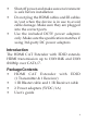
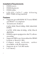
Installation Requirements 1. 2. 3. 4. HDMI source HDMI display(s) HDMI cables UTP/STP CAT6/7 cable following IEEE-T568B wiring standard Features • • • • • • • 4 Supports up to 4K @30Hz YUV 4:4:4. HDMI and HDCP 1.
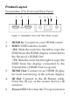
Product Layout Transmitter (TX) Front and Rear Panel 1 2 3 4 5 6 7 8 Figure 1: Transmitter Front and Rear Panel Layout 1. 2. 3. 4. 5.
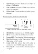
. 7. 8. RJ45 Out: Connect to the Receiver's RJ45 In using a CAT cable Link LED: On when the HDMI source device signal is detected Power Jack: Connect to the included power adapter Receiver (RX) Front and Rear Panel 1 2 3 4 5 6 Figure 2: Receiver Front and Rear Panel Layout 1. 2. 3. 4. 5. 6.
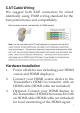
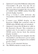
CAT Cable Wiring We suggest both RJ45 connectors be wired identically using T568B wiring standard for the best performance and compatibility. Hardware Installation 1. 2. 3. Power off all devices including your HDMI source and HDMI display(s). Connect your HDMI source device to the Transmitter's HDMI In connector with an HDMI cable (HDMI cable not included).
4. 5. 6. 7 8. 9. 10. 8 Optional: Connect the IR Blaster cable to the Transmitter's IR port. Face the IR eye towards your source device's IR window. This connection is needed only if you need to control your HDMI source from the remote display location. Plug a CAT6/7 cable between the Transmitter's RJ45 Out and Receiver's RJ45 In. Connect your HDMI display to the Receiver's HDMI Out connector with an HDMI cable (HDMI cable not included).
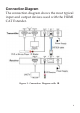
Connection Diagram The connection diagram shows the most typical input and output devices used with the HDMI CAT Extender.
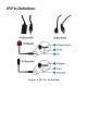
IR Pin Definition Figure 4: IR Pin Definition
Specifications 11
Disclaimer The product name and brand name may be registered trademarks of related manufacturers. TM and ® may be omitted on the user’s guide. The pictures on the user’s guide are just for reference, and there may be some slight differences with the actual products. We reserve the right to make changes without prior notice to a product or system described herein to improve reliability, function, or design. Thank you for choosing gofanco www.gofanco.