Model No. CWTL05607.1 Serial No. Write the serial number in the space above for future reference. Serial Number Decal QUESTIONS? As a manufacturer, we are committed to providing complete customer satisfaction. If you have questions, or if parts are missing, PLEASE DO NOT CONTACT THE STORE; please contact Customer Care. IMPORTANT: You must note the product model number and serial number (see the drawing above) before contacting us: CALL TOLL-FREE: 1-877-776-4777 Mon.–Fri. 6 a.m.–6 p.m. MST Sat. 8 a.m.
TABLE OF CONTENTS WARNING DECAL PLACEMENT . . . . . . . . . . . . . . . . . . . . . . . . . . . . . . . . . . . . . . . . . . . . . . . . . . . . . . . . . . . . . .2 IMPORTANT PRECAUTIONS . . . . . . . . . . . . . . . . . . . . . . . . . . . . . . . . . . . . . . . . . . . . . . . . . . . . . . . . . . . . . . . .3 BEFORE YOU BEGIN . . . . . . . . . . . . . . . . . . . . . . . . . . . . . . . . . . . . . . . . . . . . . . . . . . . . . . . . . . . . . . . . . . . . . .5 ASSEMBLY . . . . . . . . . . . . . .
IMPORTANT PRECAUTIONS WARNING: To reduce the risk of serious injury, read all important precautions and instructions in this manual and all warnings on your treadmill before using your treadmill. ICON assumes no responsibility for personal injury or property damage sustained by or through the use of this product. of carrying 15 or more amps. No other appliance should be on the same circuit. Do not use an extension cord. 1. Before beginning any exercise program, consult your physician.
20. Never leave the treadmill unattended while it is running. Always remove the key, unplug the power cord, and switch the reset/off circuit breaker to the off position when the treadmill is not in use. (See the drawing on page 5 for the location of the circuit breaker.) 24. Never insert any object into any opening on the treadmill. 25. 21. Do not attempt to raise, lower, or move the treadmill until it is properly assembled. (See ASSEMBLY on page 6, and HOW TO FOLD AND MOVE THE TREADMILL on page 23.
BEFORE YOU BEGIN Thank you for selecting the revolutionary GOLD’S GYM® MAXX CROSSWALK 650 treadmill. The MAXX CROSSWALK 650 treadmill offers an impressive array of features designed to make your workouts at home more enjoyable and effective. And when you’re not exercising, the unique MAXX CROSSWALK 650 treadmill can be folded up, requiring less than half the floor space of other treadmills. ual. To help us assist you, note the product model number and serial number before contacting us.
2 1/2” Bolt (37)–2 ASSEMBLY Wheel Nut (32)–2 3 1/2” Bolt (45)–4 To hire an authorized service technician to assemble the elliptical exerciser, call 1-800-445-2480. Handrail Bolt (64)–4 Assembly requires two persons. Set the treadmill in a cleared area and remove all packing materials. Do not dispose of the packing materials until assembly is completed. Note: The underside of the treadmill walking belt is coated with high-performance lubricant.
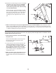
2. Hold the Right Upright (107) against the Base (108). Be careful not to pinch the Upright Wire (77). 2 107 Attach the Right Upright (107) to the Base (108) with a 3/8" x 1" Bolt (106), a 3/8" x 2 3/4" Bolt (105), and two 3/8" Star Washers (23). Do not tighten the Bolts yet. 77 108 23 105 106 3. Attach two Base Pads (82) to the Base (108) with two #8 x 1" Tek Screws (83) as shown. 3 Insert an Extension Leg (89) into the Base (108) as shown.
5. Attach two Base Pads (82) to the Base (108) with two #8 x 1" Tek Screws (83) as shown. 5 Insert the other Extension Leg (89) into the Base (108) as shown. Hold two Extension Leg Nuts (67) in the bottom of the Extension Leg. Next, insert two 5/16" x 2 1/4" Bolts (65) into the top of the Extension Leg, and firmly tighten the Bolts into the Extension Leg Nuts. 82 108 65 82 83 67 89 6.
8. Attach the Left Upper Body Arm (97) to the Left Upright (84) with two 1/4" x 4 1/2" Bolts (103), two 1/4" Flat Washers (102), and two 3/8" Star Washers (23) as shown. Make sure that the Left Upper Body Arm is on the indicated side of the Left Handrail (13). 8 Attach the Right Upper Body Arm (not shown) to the Right Upright (not shown) in the same way. 84 13 102 103 97 23 9. With the help of a second person, carefully lower the Left and Right Uprights (84, 107) to the position shown.
. Attach the Latch Housing (73) to the Left Upright (84) with two #8 x 3/4" Screws (3); start both Screws and then tighten them. Note: Make sure that the large hole in the Latch Housing is on the indicated side. 10 Remove the knob from the pin. Make sure that the collar and the spring are on the pin. (Note: If there are two collars, place one on each side of the spring.) Next, insert the pin into the Latch Housing (73). Then, tighten the knob onto the pin. 84 73 Knob Spring 3 Large Collar Hole Pin 11.
OPERATION AND ADJUSTMENT THE PRE-LUBRICATED WALKING BELT tric shock. This product is equipped with a cord having an equipment-grounding conductor and a grounding plug. Plug the power cord into a surge suppressor, and plug the surge suppressor into an appropriate outlet that is properly installed and grounded in accordance with all local codes and ordinances. Important: The treadmill is not compatible with GFCI-equipped outlets. Your treadmill features a walking belt coated with highperformance lubricant.
CONSOLE DIAGRAM Key Clip FEATURES OF THE CONSOLE during your workout. There are two whole body, two upper body, and two lower body cross trainer workouts to choose among. Note: The strength exercises require the use of dumbbells and an inflatable exercise ball (not included). To purchase dumbbells or an exercise ball, call the telephone number on the front cover of this manual. The treadmill console offers an impressive array of features designed to make your workouts more effective and enjoyable.
HOW TO TURN ON THE POWER HOW TO USE THE MANUAL MODE IMPORTANT: If the treadmill has been exposed to cold temperatures, allow it to warm to room temperature before turning on the power. If you do not do this, the console displays or other electrical components may become damaged. 1. Insert the key into the console. Plug in the power cord (see page 11). Next, locate the reset/off circuit breaker on the treadmill frame near the power cord. Make sure that the circuit breaker is in the “reset” position.
4. Change the incline of the treadmill as desired. The upper part of the display can also show the elapsed time, the distance that you have walked or run, the speed of the walking belt, the approximate number of calories you have burned while walking or running, your pace in minutes per mile, or the incline level of the treadmill. If desired, press the Display button repeatedly until the upper part of the display shows the information you are most interested in viewing.
To measure your heart rate, stand on the foot rails and hold the metal contacts on the handrail— avoid moving your hands. When your pulse is detected, one or two dashes will appear in the right side of the display and then your heart rate will be shown. For the most accurate heart rate reading, continue to hold the contacts for about 15 seconds.
HOW TO USE A CROSS TRAINER WORKOUT The same speed setting and/or incline setting may be programmed for consecutive segments.) During other segments, the console will prompt you to perform strength exercises. 1. Insert the key into the console. See HOW TO TURN ON THE POWER on page 13. During the workout, the profile will show your progress. The Current Segment flashing segment of the profile represents the current segment of the workout.
5. Continue the cross trainer workout. 4. Perform the first strength exercise when prompted. When you have performed the recommended number of repetitions, the words PRESS START will appear in the display. To continue the cross trainer workout, step onto the treadmill, slide the clip back onto the waistband of your clothes, and press the Start button. The treadmill will automatically adjust to the speed and incline settings for the next segment.
HOW TO USE A DISTANCE WORKOUT The upper left corner of the display will show the number of kilometers still to be run. When only 20 meters remain, the display will flash and a series of tones will sound. 1. Insert the key into the console. See HOW TO TURN ON THE POWER on page 13. To stop the workout at any time, press the Stop button. The time will begin to flash in the display. To restart the workout, press the Start button. The walking belt will begin to move at 1 mph.
HOW TO USE A PRESET WORKOUT the profile represents the current segment of the workout. The height of the flashing segment indicates the speed setting for the current segment. At the end of each segment, a series of tones will sound and the next segment of the profile will begin to flash. If a different speed and/or incline setting is programmed for the next sentence, the new speed and/or incline settings will flash in the display to alert you. 1. Insert the key into the console.
THE INFORMATION MODE You can adjust the volume of the personal trainer audio (0 through 5) by pressing the Incline increase button repeatedly. The volume setting appears as the upper right digit in the display. The console features an information mode that keeps track of treadmill usage information. The information mode also allows you to select miles or kilometers as the unit of measurement, to select an audio trainer setting, to adjust the volume and to turn on and turn off the demo mode.
THE OPTIONAL CHEST PULSE SENSOR An optional chest pulse sensor offers hands-free operation as it tracks your heart rate during your workouts. To purchase the optional chest pulse sensor, call the telephone number on the front cover of this manual. HOW TO ADJUST THE CUSHIONING SYSTEM Platform Cushion Remove the key from the console and unplug the power cord. The treadmill features a cushioning system that reduces the impact as you walk or run on the treadmill.
HOW TO USE THE UPPER BODY ARMS As you walk on the treadmill, you can hold the handrails or use the upper body arms. To exercise your arms, shoulders, and back for a total body workout, move the upper body arms forward and back as you walk on the treadmill. Upper Body Arms To vary the intensity of your upper body exercise, the resistance of the upper body arms can be adjusted. To increase the resistance, turn the resistance knobs clockwise; to decrease the resistance, turn the knobs counterclockwise.
HOW TO FOLD AND MOVE THE TREADMILL HOW TO FOLD THE TREADMILL FOR STORAGE Before folding the treadmill, adjust the incline to the lowest position. If you do not do this, you may damage the treadmill when you fold it. Remove the key and unplug the power cord. CAUTION: You must be able to safely lift 45 lbs. (20 kg) to raise, lower, or move the treadmill. 1. Hold the metal frame firmly in the location shown by the arrow at the right.
HOW TO LOWER THE TREADMILL FOR USE 1. Hold the upper end of the treadmill with your right hand. Pull the latch knob to the left and hold it. Pivot the frame down until the cushion is past the latch pin. Cushion Open Latch Knob Latch Pin 2. Hold the metal frame firmly with both hands, and lower it to the floor. CAUTION: To decrease the possibility of injury, do not lower the frame by gripping only the plastic foot rails. Do not drop the frame to the floor.
TROUBLESHOOTING Most treadmill problems can be solved by following the steps below. Find the symptom that applies, and follow the steps listed. If further assistance is needed, please see the front cover of this manual. PROBLEM: The power does not turn on SOLUTION: a. Make sure that the power cord is plugged into a surge suppressor, and that the surge suppressor is plugged into a properly grounded outlet (see page 11).
Raise the Uprights (84, 107) to the vertical position. Remove the three #8 x 3/4" Hood Screws (7) from the Hood (41), and carefully pivot the Hood off. 7 84 107 7 41 Locate the Reed Switch (63) and the Magnet (46) on the left side of the Pulley (47). Turn the Pulley until the Magnet is aligned with the Reed Switch. Make sure that the gap between the Magnet and the Reed Switch is about 1/8 in. (3 mm).
PROBLEM: The walking belt is off-center or slips when walked on SOLUTION: a. If the walking belt is off-center, first remove the key and UNPLUG THE POWER CORD. If the walking belt has shifted to the left, use the hex key to turn the left rear roller bolt clockwise 1/2 of a turn; if the walking belt has shifted to the right, turn the left bolt counterclockwise 1/2 of a turn. Be careful not to overtighten the walking belt. Then, plug in the power cord, insert the key, and run the treadmill for a few minutes.
EXERCISE GUIDELINES Burning Fat—To burn fat effectively, you must exercise at a low intensity level for a sustained period of time. During the first few minutes of exercise, your body uses carbohydrate calories for energy. Only after the first few minutes of exercise does your body begin to use stored fat calories for energy. If your goal is to burn fat, adjust the intensity of your exercise until your heart rate is near the lowest number in your training zone.
SUGGESTED STRETCHES The correct form for several basic stretches is shown at the right. Move slowly as you stretch—never bounce. 1. Toe Touch Stretch Stand with your knees bent slightly and slowly bend forward from your hips. Allow your back and shoulders to relax as you reach down toward your toes as far as possible. Hold for 15 counts, then relax. Repeat 3 times. Stretches: Hamstrings, back of knees and back. 1 2. Hamstring Stretch Sit with one leg extended.
PART LIST—Model No. CWTL05607.1 R0108A To locate the parts listed below, see the EXPLODED DRAWING near the end of this manual. Key No. Qty. 1 2 3 4 5 6 7 8 9 10 11 12 13 14 15 16 17 18 19 20 21 22 23 24 25 26 27 28 29 30 31 32 33 34 35 36 37 38 39 40 41 42 43 44 45 46 47 48 49 50 2 6 40 8 10 2 4 4 2 2 4 2 1 1 2 1 1 1 1 1 1 2 9 2 2 1 1 2 4 2 11 2 11 1 2 1 1 1 1 1 1 1 1 2 1 1 1 1 1 2 Description Key No. Qty.
Key No. Qty. 101 102 103 104 105 106 107 108 109 110 111 112 2 4 4 2 2 2 1 1 2 2 1 1 Description Resistance Assembly 1/4" Flat Washer 1/4" x 4 1/2" Bolt Upper Body Arm Insert 3/8" x 2 3/4" Bolt 3/8" x 1" Bolt Right Upright Base Cushion Stop Cushion Track 1/4" Nut Audio Wire Key No. Qty.
53 91 50 90 70 5 95 3 69 52 9 16 55 5 109 114 53 110 4 91 49 4 3 95 51 50 6 1 5 4 48 54 90 9 4 12 70 58 11 5 70 10 15 114 110 109 4 5 5 4 17 47 46 4 6 4 11 5 10 12 70 1 57 33 15 5 EXPLODED DRAWING A—Model No. CWTL05607.
EXPLODED DRAWING B—Model No. CWTL05607.
EXPLODED DRAWING C—Model No. CWTL05607.
EXPLODED DRAWING D—Model No. CWTL05607.
ORDERING REPLACEMENT PARTS To order replacement parts, please see the front cover of this manual.