www.workoutwarehouse.com Model No. GGBE0867.1 Serial No. Write the serial number in the space above for future reference. Serial Number Decal QUESTIONS? If you have questions, or if parts are missing, PLEASE DO NOT CONTACT THE STORE; please contact Customer Care. IMPORTANT: Please register this product (see the limited warranty on the back cover of this manual) before contacting Customer Care. 1-877-776-4777 CALL TOLL-FREE: Mon.–Fri., 6 a.m.–6 p.m. MT Sat. 8 a.m.–4 p.m. MT ON THE WEB: www.
TABLE OF CONTENTS WARNING DECAL PLACEMENT . . . . . . . . . . . . . . . . . . . . . . . . . . . . . . . . . . . . . . . . . . . . . . . . . . . . . . . . . . . . . .2 IMPORTANT PRECAUTIONS . . . . . . . . . . . . . . . . . . . . . . . . . . . . . . . . . . . . . . . . . . . . . . . . . . . . . . . . . . . . . . . .3 BEFORE YOU BEGIN . . . . . . . . . . . . . . . . . . . . . . . . . . . . . . . . . . . . . . . . . . . . . . . . . . . . . . . . . . . . . . . . . . . . . .4 PART IDENTIFICATION CHART . . . . .
IMPORTANT PRECAUTIONS WARNING: To reduce the risk of serious injury, read all important precautions and instructions in this manual and all warnings on your inversion system before using your inversion system. ICON assumes no responsibility for personal injury or property damage sustained by or through the use of the inversion system. 1. Before beginning any exercise program, consult your physician. This is especially important for persons over age 35 or persons with pre-existing health problems. 12.
BEFORE YOU BEGIN Thank you for selecting the versatile GOLDʼS GYM® INVERSION SYSTEM. The inversion system will increase your intervertebral dimension, decrease pressure on intervertebral discs, stretch and relax your muscles, and temporarily relieve back pain associated with the listed conditions. after reading this manual, please see the front cover of this manual. To help us assist you, note the product model number and serial number before contacting us.
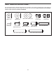
PART IDENTIFICATION CHART See the drawings below to identify small parts used in assembly. The number in parentheses by each drawing is the key number of the part, from the PART LIST near the end of this manual. Note: If a part is not in the hardware kit, check to see if it has been preattached.
ASSEMBLY • For help identifying small parts, see the PART IDENTIFICATION CHART on page 5. Make Assembly Easier This manual is designed to ensure that the inversion system can be assembled successfully by almost anyone. Most people find that if they set aside plenty of time, assembly goes smoothly. • As you assemble the inversion system, make sure that all parts are oriented as shown in the drawings. • Tighten all parts as you assemble them, unless instructed to do otherwise.
2. Attach the Front Leg Frame (5) to the Front Legs (1, 2) with four M8 x 45mm Button Bolts (43), four M8 Curved Washers (53), and four M8 Nylon Locknuts (54). Do not tighten the Nylon Locknuts yet. 2 43 1 53 53 54 54 2 3. Attach the two Bases (4) to the Front and Rear Legs (1, 2, 3) as shown with four M8 x 45mm Button Bolts (43). 5 54 54 53 43 53 3 3 3 1 43 4.
5. Attach the Foot Frame (8) to the Adjustment Frame (7) with three M8 x 15mm Buttons Screws (47). 5 7 8 47 47 6. Slide the two Large Foam Pads (32) onto the Ankle Lock (9). Next, pull the Long Adjustment Knob (20), insert the Ankle Lock (9) into the Adjustment Frame (7), and then release the Long Adjustment Knob. Make sure that the Long Adjustment Knob is engaged in the indicated adjustment hole in the Ankle Lock.
8. Orient the two Pivot Bars (14) so that the Pulleys (22) face away from the Center Frame (13). Then, insert the Pivot Bars into the brackets on the ends of the Center Frame, and engage the pins on the brackets into the center adjustment holes in the Pivot Bars. 8 22 Insert the two Pulleys (22) down into the slots in the Saddle Plates (18). Pin See step 2. Tighten the four M8 Nylon Locknuts (54). 9.
. Attach the Backrest (23) to the Backrest Frame (6) with four M6 x 18mm Button Screws (50) and four M6 Flat Washers (51). 10 23 6 51 50 51 11. Attach the Right and Left Handles (15, 16) to the Legs (1, 2, 3) with four M8 Nylon Locknuts (54).
12. Slide the Left Cover (31) onto the left Saddle Plate (18). Attach the Left Cover with a Small Knob (42). 12 30 Attach the Right Cover (30) in the same way. 13. See the inset drawings. Open the Quick Link (29) by turning the quick link nut. Then, attach one end of the Chain (28) to the indicated bracket on the Front Leg Frame (5) with the Quick Link (29). Close the Quick Link by turning the quick link nut.
ADJUSTMENT This section explains how to adjust the inversion system. See DEVELOPING A PROGRAM on page 16 for important information about how to get the most benefit from your exercise program. Make sure all parts are properly tightened each time the inversion system is used. Replace any worn parts immediately. The table can be cleaned with a damp cloth and a mild, non-abrasive detergent; do not use solvents. SELECTING A PIVOT BAR POSITION See the inset drawing.
ADJUSTING THE ADJUSTMENT FRAME The length of the Adjustment Frame (7) can be adjusted to correspond to your height. First, remove the Pin (24) from the Backrest Frame (6) and the Adjustment Frame. Pull the Short Adjustment Knob (19) as far as possible. Slide the Adjustment Frame into or out of the Backrest Frame so that the first or second measurement greater than your height is covered by the Backrest Frame. Next, engage the Short Adjustment Knob into one of the adjustment holes in the Adjustment Frame.
LOCKING THE INVERSION SYSTEM When the inversion system is not in use, it should be locked to prevent unsupervised use. Wrap the Lock Cable (62) around the Front Leg Frame (5) and the Adjustment Frame (7) as shown. Then, connect the ends of the Lock Cable with an M8 x 20mm Button Bolt (64) and an M8 Nylon Locknut (54). 5 54 7 62 64 STORING THE INVERSION SYSTEM To store the inversion system, first adjust the Adjustment Frame (7) to the shortest length (see ADJUSTING THE ADJUSTMENT FRAME on page 13).
ROTATING ON THE INVERSION SYSTEM This section explains how to rotate back on the inversion system, and then return to the starting position. Before using the inversion system, see the ADJUSTMENT section starting on page 12 to correctly set up the inversion system. ROTATING BACK ON THE INVERSION SYSTEM ROTATING UP ON THE INVERSION SYSTEM To rotate back on the inversion system, slowly lift your arms over your head until you reach the desired position.
DEVELOPING A PROGRAM This section contains information and suggestions about using the inversion system. Make sure that all parts are properly tightened each time you use the inversion system. Replace any worn parts immediately. See the ADJUSTMENT section starting on page 12 to identify parts referred to in this section. BENEFITING FROM USING THE INVERSION SYSTEM If you feel nauseated while using the inversion system, return to the starting position.
NOTES 17
PART LIST—Model No. GGBE0867.1 Key No. Qty. 1 2 3 4 5 6 7 8 9 10 11 12 13 14 15 16 17 18 19 20 21 22 23 24 25 26 27 28 29 30 31 32 33 1 1 2 2 1 1 1 1 1 1 1 2 1 2 1 1 1 2 1 1 2 2 1 1 1 1 1 1 1 1 1 2 2 Description Key No. Qty.
EXPLODED DRAWING—Model No. GGBE0867.
ORDERING REPLACEMENT PARTS To order replacement parts, please see the front cover of this manual.