Model No. GGTL03607.2 Serial No. Write the serial number in the space above for future reference. Serial Number Decal QUESTIONS? As a manufacturer, we are committed to providing complete customer satisfaction. If you have questions, or if parts are missing, PLEASE DO NOT CONTACT THE STORE; please contact Customer Care. IMPORTANT: You must note the product model number and serial number (see the drawing above) before contacting us: 1-877-776-4777 CALL TOLL-FREE: Mon.–Fri. 6 a.m.–6 p.m. MST Sat. 8 a.
TABLE OF CONTENTS WARNING DECAL PLACEMENT . . . . . . . . . . . . . . . . . . . . . . . . . . . . . . . . . . . . . . . . . . . . . . . . . . . . . . . . . . . . . .2 IMPORTANT PRECAUTIONS . . . . . . . . . . . . . . . . . . . . . . . . . . . . . . . . . . . . . . . . . . . . . . . . . . . . . . . . . . . . . . . .3 BEFORE YOU BEGIN . . . . . . . . . . . . . . . . . . . . . . . . . . . . . . . . . . . . . . . . . . . . . . . . . . . . . . . . . . . . . . . . . . . . . .5 ASSEMBLY . . . . . . . . . . . . .
IMPORTANT PRECAUTIONS WARNING: To reduce the risk of serious injury, read all important precautions and instructions in this manual and all warnings on your treadmill before using your treadmill. ICON assumes no responsibility for personal injury or property damage sustained by or through the use of this product. 1. Before beginning any exercise program, consult your physician. This is especially important for persons over the age of 35 or persons with pre-existing health problems.
24. Inspect and properly tighten all parts of the treadmill regularly. 20. Never leave the treadmill unattended while it is running. Always remove the key, unplug the power cord, and switch the reset/off circuit breaker to the off position when the treadmill is not in use. (See the drawing on page 5 for the location of the circuit breaker.) 25. 21. Do not attempt to raise, lower, or move the treadmill until it is properly assembled.
BEFORE YOU BEGIN Thank you for selecting the revolutionary GOLDʼS GYM® 450 treadmill. The 450 treadmill offers an impressive array of features designed to make your workouts at home more enjoyable and effective. And when youʼre not exercising, the unique 450 treadmill can be folded up, requiring less than half the floor space of other treadmills. ual. To help us assist you, note the product model number and serial number before contacting us.
ASSEMBLY To hire an authorized service technician to assemble the treadmill, call 1-800-445-2480. Assembly requires two persons. Set the treadmill in a cleared area and remove all packing materials. Do not dispose of the packing materials until assembly is completed. Note: The underside of the treadmill walking belt is coated with high-performance lubricant. During shipping, a small amount of lubricant may be transferred to the top of the walking belt or the shipping carton.
1. Make sure that the power cord is unplugged. With the help of a second person, carefully tip the treadmill onto its left side. Partially fold the Frame (48) so that the treadmill is more stable; do not fully fold the Frame yet. 1 Cut the tie securing the Upright Wire (77) to the Base (85). Locate the tie in the indicated hole in the Base, and use the tie to pull the Upright Wire out of the hole.
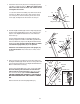
4. Hold a Bolt Spacer (79) inside the lower end of the Right Upright (78). Insert an M10 x 96mm Bolt (5) with an M10 Star Washer (8) into the Right Upright and the Bolt Spacer. Repeat this step with a second Bolt Spacer (79), M10 x 96mm Bolt (5), and M10 Star Washer (8). 4 5 78 8 Hold the Right Upright Spacer (80) and the Right Upright (78) against the Base (85). Be careful not to pinch the Upright Wire (77). Tighten the M10 x 96mm Bolts (5) with your fingers; do not fully tighten the Bolts yet.
7. Attach the Latch Insert (70) to the Left Upright (73) with two M4.2 x 19mm Screws (1). Make sure that the large hole in the Latch Insert is on the side shown. Do not overtighten the Screws. 7 72 Locate the Latch Pin Assembly (72). Remove the knob from the pin. Make sure that the collar and the spring are on the pin as shown. Insert the pin into the Latch Insert (70), and tighten the knob back onto the pin. 8.
. Set the console assembly on the Handrails (89, 90); insert the excess wiring into the Right Handrail (90). Attach the console assembly with four M4.2 x 19mm Screws (1), two 1/4" x 1/2" Bolts (9), and two 1/4" Star Washers (71) as shown. Make sure that no wires are pinched. Start all four Screws and both Bolts before tightening any of them. See steps 4 and 6. Tighten the four M10 x 96mm Bolts (5). See step 8. Tighten the six M8 x 19mm Bolts (6). 10 Console Assembly 90 1 9 71 89 1 71 9 11.
OPERATION AND ADJUSTMENT THE PRE-LUBRICATED WALKING BELT tric shock. This product is equipped with a cord having an equipment-grounding conductor and a grounding plug. Plug the power cord into a surge suppressor, and plug the surge suppressor into an appropriate outlet that is properly installed and grounded in accordance with all local codes and ordinances. Important: The treadmill is not compatible with GFCI-equipped outlets. Your treadmill features a walking belt coated with highperformance lubricant.
CONSOLE DIAGRAM Clip Key use a classic workout, see page 15. To use the weight loss workout, see page 16. To use the information mode, see page 16. FEATURES OF THE CONSOLE The treadmill console offers an impressive array of features designed to make your workouts more effective and enjoyable. IMPORTANT: If there are sheets of clear plastic on the console, remove the plastic. To prevent damage to the walking platform, wear clean athletic shoes while using the treadmill.
HOW TO TURN ON THE POWER IMPORTANT: If the treadmill has been exposed to cold temperatures, allow it to warm to room temperature before turning on the power. If you do not do this, the console displays or other electrical components may become damaged. Plug in the power cord (see page 11). Next, locate the reset/off circuit breaker on the treadmill frame near the power cord. Switch the circuit breaker to the reset position. 3. Start the walking belt.
The lower left corner of the display can show the elapsed time, the distance that you have walked or run during your workout, and the incline level of the treadmill. Note: During a classic workout, the display will show the time remaining in the program instead of the elapsed time. The lower right corner of the display can show the speed of the walking belt and the approximate number of calories that you have burned during your workout.
HOW TO USE A CLASSIC WORKOUT next segment of the profile will begin to flash. If a different speed and/or incline setting is programmed for the next sentence, the new speed and/or incline settings will flash in the display to alert you. 1. Insert the key into the console. See HOW TO TURN ON THE POWER on page 13. The workout will continue in this way until the last segment of the profile flashes in the display and the last segment ends. The walking belt will then slow to a stop. 2.
HOW TO USE THE WEIGHT LOSS WORKOUT 1. Insert the key into the console. See HOW TO TURN ON THE POWER on page 13. 2. Select a weight loss workout. To use the weight loss workout, press the Weight Loss Workouts button. Input your weight and the number of calories you wish to burn by repeatedly pressing the increase and decrease buttons next to the Enter button. Press the Enter button after each selection. Note: Once you have entered your weight, it will be saved in memory. 3.
HOW TO FOLD AND MOVE THE TREADMILL HOW TO FOLD THE TREADMILL FOR STORAGE Before folding the treadmill, adjust the incline to the lowest position. If you do not do this, you may damage the treadmill when you fold it. Remove the key and unplug the power cord. CAUTION: You must be able to safely lift 45 lbs. (20 kg) to raise, lower, or move the treadmill. 1. Hold the metal frame firmly in the location shown by the arrow at the right.
TROUBLESHOOTING Most treadmill problems can be solved by following the simple steps below. Find the symptom that applies, and follow the steps listed. If further assistance is needed, please see the front cover of this manual. PROBLEM: The power does not turn on SOLUTION: a. Make sure that the power cord is plugged into a surge suppressor, and that the surge suppressor is plugged into a properly grounded outlet (see page 11).
Remove the three M4.2 x 19mm Washer Head Screws (13) and carefully pivot the Hood (53) off. 13 53 Locate the Reed Switch (54) and the Magnet (42) on the left side of the Pulley (44). Turn the Pulley until the Magnet is aligned with the Reed Switch. Make sure that the gap between the Magnet and the Reed Switch is about 1/8 in. (3 mm). If necessary, loosen the M4.2 x 19mm Screw (1), move the Reed Switch slightly, and then retighten the Screw.
PROBLEM: The walking belt is off-center or slips when walked on SOLUTION: a. If the walking belt is off-center, first remove the key and UNPLUG THE POWER CORD. If the walking belt has shifted to the left, use the hex key to turn the left rear roller bolt clockwise 1/2 of a turn; if the walking belt has shifted to the right, turn the bolt counterclockwise 1/2 of a turn. Be careful not to overtighten the walking belt. Then, plug in the power cord, insert the key, and run the treadmill for a few minutes.
EXERCISE GUIDELINES WARNING: Before beginning this Burning Fat—To burn fat effectively, you must exercise at a low intensity level for a sustained period of time. During the first few minutes of exercise, your body uses carbohydrate calories for energy. Only after the first few minutes of exercise does your body begin to use stored fat calories for energy. If your goal is to burn fat, adjust the intensity of your exercise until your heart rate is near the lowest number in your training zone.
PART LIST—Model No. GGTL03607.2 To locate the parts listed below, see the EXPLODED DRAWING near the end of this manual. Key No. Qty. 1 2 3 4 5 6 7 8 9 10 11 12 13 14 15 16 17 18 19 20 21 22 23 24 25 26 27 28 29 30 31 32 33 34 35 36 37 38 39 40 41 42 43 44 45 46 47 48 49 50 15 4 1 1 4 6 1 4 2 6 5 18 3 2 2 2 2 1 1 2 1 7 8 2 2 1 2 4 2 2 3 2 4 1 4 2 3 6 1 2 2 1 1 1 1 1 1 1 1 2 Description Key No. Qty. M4.2 x 19mm Screw M4.2 x 25mm Screw 4mm Hex Key M4.
Key No. Qty. 101 102 103 * * * 1 1 2 – – – Description Hex Key Lift Frame/Base Ground Wire Frame Endcap 8" Blue Wire, 2F 6" Blue Wire, M/F 6" Red Wire, M/F Key No. Qty. * * * – – – Description 6" Black Wire, M/F 8" Green Wire, F/Ring Userʼs Manual *These parts are not illustrated. Specifications are subject to change without notice.
3 17 23 29 50 34 51 30 59 22 49 96 15 23 101 1 35 39 17 40 23 76 29 50 1 52 30 100 22 15 41 28 23 1 35 59 35 23 48 103 14 45 16 23 40 46 42 1 47 28 14 23 43 103 76 41 35 44 23 16 EXPLODED DRAWING A—Model No. GGTL03607.
EXPLODED DRAWING B—Model No. GGTL03607.
EXPLODED DRAWING C—Model No. GGTL03607.
EXPLODED DRAWING D—Model No. GGTL03607.
ORDERING REPLACEMENT PARTS To order replacement parts, please see the front cover of this manual.