www.workoutwarehouse.com Model No. GGTL30611.0 Serial No. Write the serial number in the space above for future reference. Serial Number Decal QUESTIONS? If you have questions, or if parts are damaged or missing, DO NOT CONTACT THE STORE; please contact Customer Care. IMPORTANT: Please register this product (see the limited warranty on the back cover of this manual) before contacting Customer Care. 1-877-776-4777 CALL TOLL-FREE: Mon.–Fri. 6 a.m.–6 p.m. MT Sat. 8 a.m.–4 p.m. MT ON THE WEB: www.
TABLE OF CONTENTS WARNING DECAL PLACEMENT . . . . . . . . . . . . . . . . . . . . . . . . . . . . . . . . . . . . . . . . . . . . . . . . . . . . . . . . . . . . . .2 IMPORTANT PRECAUTIONS . . . . . . . . . . . . . . . . . . . . . . . . . . . . . . . . . . . . . . . . . . . . . . . . . . . . . . . . . . . . . . . . .3 BEFORE YOU BEGIN . . . . . . . . . . . . . . . . . . . . . . . . . . . . . . . . . . . . . . . . . . . . . . . . . . . . . . . . . . . . . . . . . . . . . . .5 ASSEMBLY . . . . . . . . . . .
IMPORTANT PRECAUTIONS WARNING: To reduce the risk of serious injury, read all important precautions and instructions in this manual and all warnings on your treadmill before using your treadmill. ICON assumes no responsibility for personal injury or property damage sustained by or through the use of this product. 1. Before beginning any exercise program, consult your physician. This is especially important for persons over age 35 or persons with pre-existing health problems.
19. The treadmill is capable of high speeds. Adjust the speed in small increments to avoid sudden jumps in speed. 24. Inspect and properly tighten all parts of the treadmill regularly. 25. Never drop or insert any object into any opening on the treadmill. 20. Never leave the treadmill unattended while it is running. Always remove the key, unplug the power cord, and press the power switch into the off position when the treadmill is not in use.
BEFORE YOU BEGIN Thank you for selecting the new GOLDʼS GYM® TRAINER 315 treadmill. The TRAINER 315 treadmill provides an impressive selection of features designed to make your workouts at home more effective and enjoyable. this manual, please see the front cover of this manual. To help us assist you, note the product model number and serial number before contacting us. The model number and the location of the serial number decal are shown on the front cover of this manual.
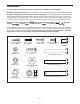
ASSEMBLY To hire an authorized service technician to assemble the treadmill, call 1-800-445-2480. Assembly requires two persons. Set the treadmill in a cleared area and remove all packing materials. Do not dispose of the packing materials until assembly is completed. Note: The underside of the treadmill walking belt is coated with high-performance lubricant. During shipping, some lubricant may be transferred to the top of the walking belt or the shipping carton.
1. Make sure that the power cord is unplugged. 1 Position the Base (52) upside-down as shown. 26 63 26 Attach four Base Feet (63) to the Base (52) with four M4.2 x 19mm Tek Screws (26). 63 52 26 63 26 63 2. Attach the Wheels (70) to the Base (52) with two M10 x 60mm Bolts (35), four Wheel Spacers (69), and two M10 Nuts (16) as shown. Do not overtighten the Nuts; the Wheels should turn freely. 2 52 35 69 16 70 69 16 69 3. Have a second person hold the Base (52) in the position shown.
4. Position the Base (52) as close to the front of the treadmill as possible, as shown. 4 See the upper inset drawing. Locate the wire tie in the lower end of the Right Upright (54). Tie the wire tie securely around the end of the Wire Harness (39). Then, locate the other end of the wire tie in the upper end of the Right Upright. Pull the upper end of the wire tie until the Wire Harness extends from the upper end of the Right Upright.
6. See the left inset drawing in step 5. Identify the outer side of the remaining Frame Spacer (11). Top View 6 Hold the Frame Spacer (11) between the Left Upright (53) and the Lift Frame (23), with the outer side of the Frame Spacer facing the Left Upright. Attach the Left Upright to the Lift Frame with an M10 x 60mm Patch Bolt (1), an M10 Flat Washer (14), and an M10 Star Washer (9); do not fully tighten the Patch Bolt yet. 1 14 9 53 53 11 23 9 1 7.
8. Start an M5 x 16mm Screw (85) with an M5 Star Washer (7) into the Right Handrail (33), and then start two M4.2 x 19mm Screws (10) into the Right Handrail. Tighten the M5 x 16mm Screw and then tighten the two M4.2 x 19mm Screws; do not overtighten the Screws. 8 85 7 33 10 Attach the Left Handrail (not shown) to the Console Assembly (91) in the same way. Note: There are no wires on the left side. 91 9.
10. Set the Console Assembly (91) on the Right Upright (54) and the Left Upright (53). Start four M8 x 15mm Bolts (8) with four M8 Star Washers (5) into the Uprights. Then, firmly tighten all four Bolts. 10 91 8 5 5 8 53 5 54 8 5 11. With the help of a second person, carefully lower the Left Upright (not shown) and the Right Upright (54) to the floor. 11 Attach the ground wire on the Wire Harness (39) to the indicated hole in the Base (52) with an M4 x 10mm Ground Screw (84).
. See the lower drawing. Position the Uprights (53, 54) so that the Frame (51) is centered between them. 12 Firmly tighten the two M10 x 60mm Patch Bolts (1) and the four M10 x 58mm Bolts (2) (only one side is shown). Be careful not to overtighten the M10 x 60mm Patch Bolts. 2 51 Raise the Uprights (53, 54). Top View 54 13. Attach the Latch Housing (48) to the Left Upright (53) with two #10 x 1" Tek Screws (13); start both Tek Screws, and then tighten each of them.
OPERATION AND ADJUSTMENT THE PRE-LUBRICATED WALKING BELT that is properly installed and grounded in accordance with all local codes and ordinances. IMPORTANT: The treadmill is not compatible with GFCI-equipped outlets. Your treadmill features a walking belt coated with highperformance lubricant. IMPORTANT: Never apply silicone spray or other substances to the walking belt or the walking platform. Such substances will cause excessive wear.
CONSOLE DIAGRAM Key Clip FEATURES OF THE CONSOLE IMPORTANT: If there is a sheet of plastic on the face of the console, remove the plastic. To prevent damage to the walking platform, wear clean athletic shoes while using the treadmill. The first time the treadmill is used, observe the alignment of the walking belt, and center the walking belt if necessary (see page 21). The treadmill console offers a selection of features designed to make your workouts more effective.
HOW TO TURN ON THE POWER HOW TO USE THE MANUAL MODE IMPORTANT: If the treadmill has been exposed to cold temperatures, allow it to warm to room temperature before turning on the power. If you do not do this, you may damage the console displays or other electrical components. Plug in the power cord (see page 13). Next, locate the power switch on the treadmill frame near the power cord. Make sure that the switch is in the reset position. 1. Insert the key into the console.
5. Follow your progress with the displays. 6. Measure your heart rate if desired. The lower left display—As you exercise, the lower left display can show the elapsed time, the distance that you have walked or run, and the incline level of the treadmill each time the incline level changes. Note: When a preset workout is selected, the display will show the time remaining in the workout instead of the elapsed time. Before using the handgrip pulse sensor, remove the sheets of plastic from the metal contacts.
HOW TO USE A PRESET WORKOUT The workout will continue in this way until the last segment ends. The walking belt will then slow to a stop. 1. Insert the key into the console. See HOW TO TURN ON THE POWER on page 15.
THE INFORMATION MODE An “E” for English miles or an “M” for metric kilometers will appear in the lower right display. Press the Speed increase button to change the unit of measurement, if desired. The console features an information mode that keeps track of treadmill usage information and allows you to select a unit of measurement for the console. You can also turn on and turn off the display demo mode.
HOW TO FOLD AND MOVE THE TREADMILL HOW TO FOLD THE TREADMILL To avoid damaging the treadmill, adjust the incline to the lowest position before you fold the treadmill. Then, remove the key and unplug the power cord. CAUTION: You must be able to safely lift 45 lbs. (20 kg) to raise, lower, or move the treadmill. 1. Hold the metal frame firmly in the location shown by the arrow below. CAUTION: Do not hold the frame by the plastic foot rails. Bend your legs and keep your back straight.
TROUBLESHOOTING Most treadmill problems can be solved by following the steps below. Find the symptom that applies, and follow the steps listed. If further assistance is needed, see the front cover of this manual. PROBLEM: The power does not turn on SOLUTION: a. Make sure that the power cord is plugged into a surge suppressor, and that the surge suppressor is plugged into a properly grounded outlet (see page 13).
PROBLEM: The walking belt slows when walked on SOLUTION: a. Use only a single-outlet surge suppressor that meets all of the specifications described on page 13. b. If the walking belt is overtightened, treadmill performance may decrease and the walking belt may become damaged. Remove the key and UNPLUG THE POWER CORD. Using the hex key, turn both idler roller bolts counterclockwise, 1/4 of a turn.
EXERCISE GUIDELINES WARNING: Before beginning this or any exercise program, consult your physician. This is especially important for persons over age 35 or persons with pre-existing health problems. The pulse sensor is not a medical device. Various factors may affect the accuracy of heart rate readings. The pulse sensor is intended only as an exercise aid in determining heart rate trends in general. These guidelines will help you to plan your exercise program.
PART LIST Key No. Qty. 1 2 3 4 5 6 7 8 9 10 11 12 13 14 15 16 17 18 19 20 21 22 23 24 25 26 27 28 29 30 31 32 33 34 35 36 37 38 39 40 41 42 43 44 45 46 47 48 49 50 51 52 2 6 2 6 4 1 2 4 6 12 4 1 2 2 1 4 1 1 4 3 6 1 1 1 6 4 2 4 2 2 1 2 1 2 2 2 1 2 1 1 4 4 1 6 2 1 3 1 2 4 1 1 Description Key No. Qty. M10 x 60mm Patch Bolt M10 x 58mm Bolt M4.2 x 13mm Tek Screw M4.2 x 16mm Screw M8 Star Washer Latch Warning Decal M5 Star Washer M8 x 15mm Bolt M10 Star Washer M4.
75 29 24 60 95 36 21 42 27 10 19 45 102 25 74 44 4 6 29 36 64 67 97 55 95 21 42 50 25 10 61 19 78 44 44 27 93 25 51 75 102 76 19 45 11 86 28 16 83 41 62 89 71 3 25 101 46 78 56 28 68 50 19 41 43 25 94 16 44 101 41 93 31 11 17 81 41 18 96 25 EXPLODED DRAWING A Model No. GGTL30611.
EXPLODED DRAWING B Model No. GGTL30611.
EXPLODED DRAWING C Model No. GGTL30611.
EXPLODED DRAWING D Model No. GGTL30611.
ORDERING REPLACEMENT PARTS To order replacement parts, please see the front cover of this manual.