Compass ™ Owner’s Manual Compass ™ Center-Wheel Drive Power Chair GP600 SS/GP601 SS GP600 CC/GP601 CC 401 Bridge Street, Old Forge PA 18518 Tel: (800) 624-6374 Fax: (800) 628-5165 www.goldentech.
Compass Owner’s Manual – Models # : GP600 SS, GP600 CC, GP601 SS, GP601 CC Revised 11/30/06 FOR YOUR RECORDS Please fill in your Compass™ information below. This information will be useful in the event that you ever need to contact Golden Technologies, Inc. concerning your power chair. Your Compass ™ Model __________________ Serial Number _______________ Date of Purchase _______ Body Color __________________ Options ________________ Your Golden Technologies, Inc.
Compass Owner’s Manual – Models # : GP600 SS, GP600 CC, GP601 SS, GP601 CC Revised 11/30/06 CONTENTS INTRODUCTION …………………………………………………… 4 SAFETY..............................................................……….. 5-7 EMI/RFI ........................................................…….…….. 8 SPECIFICATIONS…………………………………………………… 9 ASSEMBLY…………………………………………………………… 10-14 COMFORT SETTINGS…………………………………………….. 15-20 OPERATION/DIAGNOSTICS ……………………………………. 21-26 BATTERY CHARGING …………………………………………….
Compass Owner’s Manual – Models # : GP600 SS, GP600 CC, GP601 SS, GP601 CC Revised 11/30/06 INTRODUCTION Congratulations on the purchase of your new Compass™ power chair. The Center-wheel drive Compass™ combines cutting-edge technology with an attractive design that is also highly functional in today’s world. We at Golden Technologies, Inc.
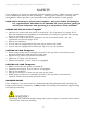
Compass Owner’s Manual – Models # : GP600 SS, GP600 CC, GP601 SS, GP601 CC Revised 11/30/06 SAFETY Your Compass™ is a battery-operated personal mobility vehicle. Please exercise caution and consideration when you are operating it. Driving your Compass™ carefully and thoughtfully will help ensure your personal safety and the safety of other people. NOTE: Before learning to operate your Compass™, have your Golden Technologies, Inc.
Compass Owner’s Manual – Models # : GP600 SS, GP600 CC, GP601 SS, GP601 CC Revised 11/30/06 SAFETY DRIVING ON AN INCLINE ♦ ♦ ♦ ♦ ♦ ♦ ♦ Drive with caution when attempting to negotiate any incline, even handicap access ramps. Always climb or descend a gradient by driving straight up or straight down the face of the slope. Do not traverse or drive across the face of a gradient.
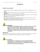
Compass Owner’s Manual – Models # : GP600 SS, GP600 CC, GP601 SS, GP601 CC Revised 11/30/06 SAFETY ♦ Do not attempt to use your Compass™ on an escalator. Always use an elevator. ♦ Do not carry passengers on your power chair. ♦ Do not operate your Compass™ if it is not functioning properly. ♦ Use caution when driving on soft or uneven surfaces such as grass, gravel, and on decks where there is no railing. ♦ Never drive on the roadway, except when you must cross the street.
Compass Owner’s Manual – Models # : GP600 SS, GP600 CC, GP601 SS, GP601 CC Revised 11/30/06 EMI/RFI The rapid development of electronics, especially in the area of communications, has saturated our environment with electromagnetic (radio) waves that are emitted by television transmitters, cellular phones, citizen’s band radios (CBs), amateur radios (ham radios), wireless computer links, microwave transmitters, paging transmitters, etc.
Compass Owner’s Manual – Models # : GP600 SS, GP600 CC, GP601 SS, GP601 CC Revised 11/30/06 SPECIFICATIONS Weight Base Seat Arms Seat (18 X 18 Solid Pan Seat) Seat (18 X 18 Captain's Chair Seat) Batteries (each) .
Compass Owner’s Manual – Models # : GP600 SS, GP600 CC, GP601 SS, GP601 CC Revised 11/30/06 ASSEMBLY Your Compass™ is shipped partially disassembled in order to maximize the protection of all its parts during the shipping process. Please follow the instruction below to quickly and easily assemble the power chair for your use. NOTE: You will need only basic tools.
Compass Owner’s Manual – Models # : GP600 SS, GP600 CC, GP601 SS, GP601 CC Revised 11/30/06 ASSEMBLY JOYSTICK INSTALLATION 1. Position the joystick on the joystick bracket. Match the holes in the joystick with the holes in the bracket. See figure 1. 2. Insert the 4 Allen-head screws with lock washers through the bracket and into the holes in the joystick. 3. Use an Allen wrench to tighten the screws. 4. Connect the joystick cable to the controller cable. See figure 2. 5.
Compass Owner’s Manual – Models # : GP600 SS, GP600 CC, GP601 SS, GP601 CC Revised 11/30/06 ASSEMBLY SEAT REMOVAL/INSTALLATION Note: The seat assembly weighs about 48 pounds. Please ask for help if you do not feel capable of safely lifting that much weight. Removal of arms will significantly reduce the weight of seat. REMOVAL 1. Disconnect the controller cable from the joystick. “Unclip” from arm and remove Velcro® tie-wraps. See figure 2 on page 11. 2.
Compass Owner’s Manual – Models # : GP600 SS, GP600 CC, GP601 SS, GP601 CC ASSEMBLY Accessing the batteries After removing the seat, locate the (2) “Battery Box Cover Locks”. Depress both locks and lift the cover. Note: On the inside of the battery box cover there is a battery connection diagram.
Compass Owner’s Manual – Models # : GP600 SS, GP600 CC, GP601 SS, GP601 CC Revised 11/30/06 ASSEMBLY BATTERY INSTALLATION Note: The batteries weigh 24 to 39 pounds each (depending on type). Please ask for help if you do not feel capable of safely lifting that much weight. Figure 7 Figure 8 Figure 9 1. Place the batteries in the battery box. Be certain to position the terminals on each battery toward the front of the unit as shown in Figure 7.
Compass Owner’s Manual – Models # : GP600 SS, GP600 CC, GP601 SS, GP601 CC Revised 11/30/06 COMFORT SETTINGS You may be spending a great deal of time on your Compass™. To provide you with the maximum seating comfort, Golden Technologies, Inc. has designed this power chair to incorporate the following adjustments for operator comfort. COMFORT SETTINGS 1. Seat height 2. Headrest height 3. Backrest angle 4. Footrest angle 5. Footrest height 6. Joystick bracket length 7.
Compass Owner’s Manual – Models # : GP600 SS, GP600 CC, GP601 SS, GP601 CC Revised 11/30/06 COMFORT SETTINGS Adjusting the seat with a front to rear angle Bottom of Seat Seat Guide Adjusting Bolts Loosen seat guide adjusting bolts using a 6mm Allen wrench provided in the charger bag and a pair of pliers or a 13mm open end wrench. Place the seat receivers in the lowest position and insert the ball detent pins through the towers and seat receiver legs. Leave the seat guide adjusting bolts loose.
Compass Owner’s Manual – Models # : GP600 SS, GP600 CC, GP601 SS, GP601 CC Revised 11/30/06 COMFORT SETTINGS HEADREST HEIGHT ADJUSTMENT 1. Push and then release the clamp on the left post of the headrest while you are pulling up or pushing down on the head rest. See figure 10. 2. The headrest will “click” to a stop in one of the preset positions. 3. Repeat step 1 until the headrest is at the desired height.
Compass Owner’s Manual – Models # : GP600 SS, GP600 CC, GP601 SS, GP601 CC Revised 11/30/06 COMFORT SETTINGS FOOTREST ANGLE ADJUSTMENT 1. Fold the footrest upward for easy access to the angle adjustment bolt. See figure 12. 2. Use a wrench to turn the adjustment bolt counterclockwise to increase the footrest angle. 3. Use a wrench to turn the adjustment bolt clockwise to decrease the footrest angle. Footrest Angle Adjustment Bolt Figure 12 FOOTREST HEIGHT ADJUSTMENT 1. Remove front cover. 2.
Compass Owner’s Manual – Models # : GP600 SS, GP600 CC, GP601 SS, GP601 CC Revised 11/30/06 COMFORT SETTINGS FOOTREST EXTENDING Refer to the pictures below. 1. Lift the rubber pad from the footrest plate. 2. Loosen the (2) footrest adjustment screws. 3. Slide the footrest plate to the desired position and tighten the adjustment screws. NOTE: The maximum extended length is not at the end of the slots. FOOTREST EXTENSION ADJUSTMENT 1. 2. 3. 4. Place the footrest extension onto the footrest as shown below.
Compass Owner’s Manual – Models # : GP600 SS, GP600 CC, GP601 SS, GP601 CC Revised 11/30/06 COMFORT SETTINGS Joystick Holder Joystick Bracket Figure 14 Joystick Position Set Screw Armrest Height Adjustment Knob Figure 15 Armrest Width Adjustment Knobs Figure 16 ARMREST HEIGHT ADJUSTMENT 1. Loosen “Armrest Height Adjustment Knob” (Figure 14) until you can pull it outward. Note: The knob is retained in its housing with a spring. 2.
Compass Owner’s Manual – Models # : GP600 SS, GP600 CC, GP601 SS, GP601 CC Revised 11/30/06 OPERATION Your Compass™ is simple to operate. However, for your safety and the safety of others, Golden Technologies, Inc. recommends that you carefully read and understand the following operating instructions. We also recommend that you practice operating your Compass™ in an area free of any obstacles.
Compass Owner’s Manual – Models # : GP600 SS, GP600 CC, GP601 SS, GP601 CC Revised 11/30/06 OPERATION The Speed Control Buttons These buttons provide you with a way to control the maximum speed of your Compass™. ♦ Press the “turtle” button repeatedly to set your chair’s speed to the slowest setting (recommended for indoor operation). Slowest speed is indicated by one (1) lit LED section on the speed indicator scale. ♦ Press the “rabbit” button repeatedly to set your chair’s speed to its highest setting.
Compass Owner’s Manual – Models # : GP600 SS, GP600 CC, GP601 SS, GP601 CC Revised 11/30/06 OPERATION The Joystick Display The joystick display (see figure 17 on page 22) is a multifunctional visual display. This display provides three types of information. 1. On/Off status 2. Battery charge level 3. Fault diagnostics 1. On/Off Status When you turn on the power to your Compass™, the LED array will light up (see figure 17 on page 22).
Compass Owner’s Manual – Models # : GP600 SS, GP600 CC, GP601 SS, GP601 CC Revised 11/30/06 OPERATION/DIAGNOSTICS Flash codes indicate the nature of an abnormal condition directly from the SHARK Information Gauge. Without the use of any servicing tools, the condition can be simply diagnosed. Flash Description Code 1 User Fault 2 Battery Fault 3 Right Motor Fault 4 5 6 7 8 9 10 Possible stall timeout or user error. Release the joystick to neutral and try again. Check the batteries and cabling.
Compass Owner’s Manual – Models # : GP600 SS, GP600 CC, GP601 SS, GP601 CC Revised 11/30/06 OPERATION Figure 18 Figure 19 FREEWHEEL MODE ♦ To disengage the gears and put your power chair in freewheel mode, turn the freewheel levers as shown. See figure 18. ♦ To re-engage the gears and take your chair out of freewheel mode, turn the levers as shown. See figure 19. 1. Never put your power chair in freewheel mode when it is on a slope or incline of any type. 2.
Compass Owner’s Manual – Models # : GP600 SS, GP600 CC, GP601 SS, GP601 CC Revised 11/30/06 OPERATION Reset Button (circuit breaker) Figure 20 Reset Button If the main circuit breaker trips, please wait for approximately 1 minute and then push the reset button to reset the main circuit breaker. See figure 20. NOTE: Usually, the thermal rollback feature is more sensitive than the main circuit breaker.
Compass Owner’s Manual – Models # : GP600 SS, GP600 CC, GP601 SS, GP601 CC Revised 11/30/06 BATTERY CHARGING You must use only the charger that is supplied with your Compass™. The use of any other charger on this power chair will void the warranty. Using unauthorized chargers may also result in severe damage to the batteries and/ or damage to the chair. Using the wrong charger may also be a fire hazard.
Compass Owner’s Manual – Models # : GP600 SS, GP600 CC, GP601 SS, GP601 CC Revised 11/30/06 CARE AND MAINTENANCE Your Compass™ is designed to require minimal maintenance. We recommend that you periodically check the following: Tire Tread: Regularly visually inspect the tire tread. If the remaining tread is less than 1/32 of an inch, have your local Golden representative replace the worn tires. Motor Brushes: Have your local Golden representative inspect the motor brushes once a year.
Compass Owner’s Manual – Models # : GP600 SS, GP600 CC, GP601 SS, GP601 CC Revised 11/30/06 DISASSEMBLY : Make certain that the controller power is turned off and that the chair is NOT in freewheel mode before attempting to perform disassembly. SEAT REMOVAL 1. Disconnect the joystick cable from the controller cable. 2. See page 12 to complete the removal. BATTERY REMOVAL For Transportation After removing the seat and battery box cover: 1. Disconnect the battery connectors and unfasten battery straps.
Compass Owner’s Manual – Models # : GP600 SS, GP600 CC, GP601 SS, GP601 CC Revised 11/30/06 WARRANTY LIFETIME WARRANTY: ♦ Power chair frame Golden Technologies, Inc. will repair the frame with new or refurbished parts, free of charge, in the USA, in the event of defective materials or workmanship. ONE-YEAR LIMITED WARRANTY ♦ Electronic controller ♦ Drive train components Golden Technologies, Inc.
Compass Owner’s Manual – Models # : GP600 SS, GP600 CC, GP601 SS, GP601 CC Revised 11/30/06 GOLDEN Compass™ Warranty Registration Please type or print.
Compass Owner’s Manual – Models # : GP600 SS, GP600 CC, GP601 SS, GP601 CC Revised 11/30/06 401 Bridge Street, Old Forge PA 18518 Tel: (800) 624-6374 Fax: (800) 628-5165 www.goldentech.com Y O U R L I F E I N M O T I O N CompassOwner’sManual.