Walgreens Installation Guide G-1-2002-2B Walgreens Installation Guide 2B.doc 7) Determine the antenna placement in the stock room. The standard locations for the antennae are: Rx-16 should be located near the receiving door at the start of the conveyor belt. Tx-4 should be over the floor about half way down the conveyor belt (approximately half way between Rx 15 and Rx 16) Rx-15 is at the opposite end of the conveyor belt.
Walgreens Installation Guide G-1-2002-2B Walgreens Installation Guide 2B.doc Determine the Cable Pulls: After completing the other components of the Pre-Installation Store Survey, then determine the cable lengths and how to pull the coaxial cables in the store. Please review the Cable Pull section in this guide for more detailed information on pulling the cables. Factors that must be considered when determining your cable pulls are: 1) Minimize the number of cables pulls.
Walgreens Installation Guide G-1-2002-2B Walgreens Installation Guide 2B.doc Pre-Installation Store Survey Check Off Form Status Process Pre-Installation Store Survey Check Off Form Task CMU Determine the CMU location Determine the location of uninterrupted power for the CMU. Determine the location of the network connection. Primary MEU Determine the location of uninterrupted power for the MEU. Determine the access for the power cable to the power location. Determine the MEU location.
Walgreens Installation Guide G-1-2002-2B Walgreens Installation Guide 2B.doc Installation: The following workflow is only a suggested division of labor and flow of the work during an installation. Each installation crew can adjust the tasks for each member to be more efficient for that team. This example is for a back stockroom. The stock room cables would be pulled with the back pull. If you have a side stock room the center pull including the stock room should be the second pull completed.
Walgreens Installation Guide G-1-2002-2B Walgreens Installation Guide 2B.doc Installation Prep: 1) Unpack the Installation Kit and review its contents. 2) Sort the installation kit into the following categories: Rx/ARA Antennas Tx/ATA Antennas CMU MEU Power Supplies and power cables 25 foot cables 50 foot cables 85 foot cables 110 foot cables 3) Place a corresponding grid label on the side of each Rx/ARA that will be installed in the store.
Walgreens Installation Guide G-1-2002-2B Walgreens Installation Guide 2B.doc Correct Label position. In-correct Label Position Cable labels Cable lengths are marked on the cable 02C85 = 85’ cable 002C-25 = 25’ cable 7) As the cables are being labeled place all the cables and the associated Rx/ARA and Tx/ATA antennas for a cable pull in one pile. For example a 10 aisle store with a back stock room may require four cable pulls.
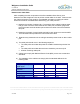
Walgreens Installation Guide G-1-2002-2B Walgreens Installation Guide 2B.doc The following table is an EXAMPLE of typical cable lengths and corresponding labels. This example shows how the cable lengths to each antenna will change in the same store based upon the location of the MEU and the power source location. The labels for the cable should always represent the mapped location on the floor plan for each antenna. The example below is a 10 aisle store with a back stock room.
Walgreens Installation Guide G-1-2002-2B Walgreens Installation Guide 2B.doc CMU Installation: 1) The CMU will be the first device installed. Do not install the antennas on the CMU and MEU until the completion of the system test by the Help Desk. 2) Mount the CMU on the wall at the location designated during the Pre-installation survey using the following instructions: a) Hold the CMU on the wall at the designated location and mark the location of the mounting brackets with a pencil.
Walgreens Installation Guide G-1-2002-2B Walgreens Installation Guide 2B.doc Do not unplug any power cords or network patch cables in either the Catalina Cabinet or the free standing Communications cabinet. 3) This step is only required for a Catalina cabinet, a) If the CMU is located in the Pharmacy proceed to step 4. b) Open the Catalina cabinet. c) Open the knock out hole selected during the pre-installation survey. The knock out hole must be on either side of the cabinet.
Walgreens Installation Guide G-1-2002-2B Walgreens Installation Guide 2B.doc g) Plug the CMU/MEU power supply cable into the designated 2-hour uninterrupted power outlet. Be certain the CMU power switch is in the OFF position. h) Proceed to Step 5. Use or disclosure of this document is covered under the Non-Disclosure Agreement executed between the reader and Goliath Solutions, LLC. This document and the information contained herein are privileged and should only be viewed by expressly authorized parties.
Walgreens Installation Guide G-1-2002-2B Walgreens Installation Guide 2B.doc 4) This step is only required with a free standing communications cabinet in the Pharmacy. a) Follow the Pharmacy access policy located in Chapter 1 under the Walgreens Environment Section. The CIT must always be escorted by a Pharmacist when in the Pharmacy. b) Open the communications cabinet.
Walgreens Installation Guide G-1-2002-2B Walgreens Installation Guide 2B.doc Gender changer cable 7) Power on the CMU and MEU and observe the lights on the CMU and MEU. Initially the ASC light will be on solid amber for about 15 seconds and then it will flash about every 30 seconds. When ASC light is flashing it indicates the CMU and MEU are communicating correctly. ASC 8) The ON light on the CMU should be a solid green.
Walgreens Installation Guide G-1-2002-2B Walgreens Installation Guide 2B.doc CMU Power Brick Power Outlet 10) The Help Desk will now perform the system test with the CMU and MEU while you continue the installation. 11) The Help Desk will call you upon completion of their system test. The MEU can then be powered down, disconnected from the CMU and moved to its permanent location any time after the completion of the system test.
Walgreens Installation Guide G-1-2002-2B Walgreens Installation Guide 2B.doc Cable Pulls: The following two examples are of the most common floor plans for a cable pull for a 9aisle store. In the first example, the MEU will be mounted on the post in Aisle 8 and the CMU will be installed near the network switch located in the store’s photo lab. The power for the MEU is coming from the CMU in the front of the store in the Photo area.
Walgreens Installation Guide G-1-2002-2B Walgreens Installation Guide 2B.doc In the second example, the MEU will be mounted on the post in Aisle 4 and the CMU installed by the network switch located in the store’s photo lab. The power for the MEU is coming from an open outlet in the ceiling near the security screen that is located by the front entrance of the store. Back Stock Room (Example using four pulls) 1) Front Pull – consists of cables 1, 3, 4, 21, and power.
Walgreens Installation Guide G-1-2002-2B Walgreens Installation Guide 2B.doc Cable Installation Requirements: The following requirements are the minimal standards for any installation of the GOLIATH System within the Walgreens Environment. Please review the “Best Practice Do’s and Don’ts” which are found in the Appendix B- Support Documents. The mandatory standards are: All cables must be run through the roof girders.
Walgreens Installation Guide G-1-2002-2B Walgreens Installation Guide 2B.doc Other important requirements are, but are not limited to: Do not bend cables at a sharp 90 degree angle since this will damage the cables. Care must be taken not to over tighten the cable ties so the internal cable does not break. Cable Pull Procedure: 1) All cables must be labeled approximately 6 inches from each end of the cable.
Walgreens Installation Guide G-1-2002-2B Walgreens Installation Guide 2B.doc Cables uncoiled close to the kick-plate of shelving unit. “Correct Method” “In-correct Method” Cables coiled in center of an aisle are a hazard. “Correct Method” “Be careful when pulling cables around a corner. They can easily snag on the corner of the end cap.” NOTE: It is easier to run this cable if it is uncoiled prior to attempting a pull.
Walgreens Installation Guide G-1-2002-2B Walgreens Installation Guide 2B.doc 4) Begin running the supplied cable through the roof girders as efficiently as possible while utilizing Best Practices. Coaxial cables are easily broken. If you pinch the line or bend it tightly, the innercore will break (the shielding will appear stressed). To ensure this does not happen, it is best to uncoil the cable prior to beginning the cable pull.
Walgreens Installation Guide G-1-2002-2B Walgreens Installation Guide 2B.doc 7) Cables running greater than 110 feet will require an F to F BNC coupling to a second cable. Use ONLY a 25 foot coaxial cable for extension: Tx/ATA antennas can only support cable lengths up to 110 feet. Rx/ARA antennas can only support cable lengths up to 135 feet. Only use the BNC coupling and 25 foot coaxial cable to extend a 110 foot coaxial cable.
Walgreens Installation Guide G-1-2002-2B Walgreens Installation Guide 2B.doc Correct Cable Installations: Cables run along length of girder in j-hooks. Cables run through Roof Girders Use or disclosure of this document is covered under the Non-Disclosure Agreement executed between the reader and Goliath Solutions, LLC. This document and the information contained herein are privileged and should only be viewed by expressly authorized parties.
Walgreens Installation Guide G-1-2002-2B Walgreens Installation Guide 2B.doc In-Correct Cable Installations (Violations): Violations Cables not run through Roof Girders Cables under AC duct work Cable touching lighting fixture Cable touching ceiling tiles Violations Cables touching water pipe Violations Cables attached to the water pipe Use or disclosure of this document is covered under the Non-Disclosure Agreement executed between the reader and Goliath Solutions, LLC.
Walgreens Installation Guide G-1-2002-2B Walgreens Installation Guide 2B.
Walgreens Installation Guide G-1-2002-2B Walgreens Installation Guide 2B.doc CMU/MEU Power Cable: 1) The CMU/MEU Power Cable will be pulled to one of three locations. The approved locations are: The first choice is an open outlet in the ceiling near the security screen that is located by the front entrance of the store. Use this location if it is available. This location requires a CMU/MEU Power Supply. The second choice is the output power port on the back of the CMU.
Walgreens Installation Guide G-1-2002-2B Walgreens Installation Guide 2B.doc 5) When pulling the CMU/MEU Power Cable to the CMU location the following requirements must be met. The CMU/MEU Power Cable must use the same entry method into the Catalina cabinet as the network cables. If a pull string is in the ceiling above photo going into the Catalina Cabinet, the CIT can use this string to pull the cables into the cabinet.
Walgreens Installation Guide G-1-2002-2B Walgreens Installation Guide 2B.doc Tx/ATA Installation: Installation of the Transmitter antennae (Tx/ATA) in the store: See Appendix A - Antenna Placement for specific antenna placement instructions and/or restrictions. Three Tx/ATA antennas will be installed over the Sales Floor (front, center, and rear). One Tx/ATA will be installed in Stock Room. The location of the Tx/ATA should be placed directly over the flooring, not over any fixtures or tables.
Walgreens Installation Guide G-1-2002-2B Walgreens Installation Guide 2B.doc Installation of the Transmitters (Tx/ATA) over the Sales Floor: 1) Installation of the transmitters will require cutting a hole in the ceiling tile. Be careful to center the antenna between any adjacent fixtures. The Tx/ATA must always be placed on a full-size ceiling tile. This allows this tile to be relocated more easily if needed. 2) Use a 1-3/8” hole saw.
Walgreens Installation Guide G-1-2002-2B Walgreens Installation Guide 2B.doc Tx install correctly in the ceiling tile In-correct installation Violations Tx Antenna Installed directly over metal shelving unit View of Tx in ceiling with service loop Use or disclosure of this document is covered under the Non-Disclosure Agreement executed between the reader and Goliath Solutions, LLC.
Walgreens Installation Guide G-1-2002-2B Walgreens Installation Guide 2B.doc Installation of the Tx/ATA antenna in the Stock Room: 1) Verify that the cable will reach the designated antenna location. 2) Mount the Tx/ATA to the roof girder at the designated location using cable ties. The Tx/ATA must always be plumb. The Tx/ATA and cable cannot touch any power conduit or any other pipes. The Tx/ATA must have a clear line-of-sight from the center of the antenna directly to the floor.
Walgreens Installation Guide G-1-2002-2B Walgreens Installation Guide 2B.doc In-Correct Tx/ATA Installation Stock Room (Violations): Violations Service loop is below roof girder Cable touches water pipe (Nee Use or disclosure of this document is covered under the Non-Disclosure Agreement executed between the reader and Goliath Solutions, LLC. This document and the information contained herein are privileged and should only be viewed by expressly authorized parties.
Walgreens Installation Guide G-1-2002-2B Walgreens Installation Guide 2B.doc Rx/ARA Installation: Installation of the Receiver antennae (Rx/ARA) over the Sales Floor: See Appendix A - Antenna Placement for specific antenna placement instructions and restrictions. Twelve to fourteen Rx/ARA antennas will be installed over the Sales Floor. Two Rx/ARA antennas will be installed in the Stock Room. The antenna locations were determined by the store survey already performed by the Lead Technician.
Walgreens Installation Guide G-1-2002-2B Walgreens Installation Guide 2B.doc Installation of the Rx/ARA over the Sales Floor: 1) At the designated location for the Rx/ARA make one hole using either an awl or #1 Phillips screwdriver in the exposed side of the ceiling tile. The hole should not be near the edge of the ceiling tile so you don’t accidentally break the tile. The hole should be a minimum of 6 inches from the edge of the tile.
Walgreens Installation Guide G-1-2002-2B Walgreens Installation Guide 2B.doc Internal view of mounting clip on installed Rx Mounting clip 4) Create the service loop per the previously stated standard and then connect the coaxial cable to the antenna. The self supporting service loop must be secured by a minimum of two cable ties. It should be 12 inches above the ceiling tile if possible.