Audio and Video door entry system digital installation with coded panel Stadio Plus Instructions manual T3403ML rev.
105 INTRODUCTION First of all we would like to thank and congratulate you for the purchase of this product manufactured by Golmar. The commitment to reach the satisfaction of our customers is stated through the ISO-9001 certification and for the manufacturing of products like this one. Its advanced technology and exacting quality control will do that customers and users enjoy with the legion of features this system offers.
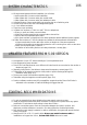
SYSTEM CHARACTERISTICS 106 O Microprocessed systems with bus installation (no call wires): wAudio system with 4 common wires installation. wVideo system with 3 common wires plus coaxial cable. wVideo system with 4 common wires plus twisted pair cable. O Unlimited number of door panels being not necessary the use of switching units. O Acoustic busy channel and call acknowledgement signals. O d.c. lock releases activation. O Timed door open activation.
107 SYSTEM OPERATION One building systems. O To make a call, the visitor should key-in the three digits code corresponding to the apartment he wishes to contact: the door panel display will show the sequence keyed-in. Once the code has been introduced, press bell key to confirm the call: acoustic tones will be heard confirming the call is in progress and the door panel display will show the message calling. At this moment the call will be received at the monitor (telephone) in the dwelling.
108 DOOR PANEL INSTALLATION E mbedding box positioning. 1850 1450 1650 The upper part of the door panel should be placed at 1,65m. height roughly. The hole dimensions will depend on the number of door panel modules. Modules Model 1 CE610 2 CE620 3 CE630 W H D 125 140 56 125 257 56 125 mm. 374 mm. 56 mm. The door panel has been designed to be placed under most of the environmental conditions. However it's recommended to take additional cautions like rainproof covers.
109 DOOR PANEL INSTALLATION P lace the embedding box. Pass the wiring through the hole made in the bottom part of the embedding box. Level and flush the embedding box. Once the embedding box is placed, remove the protective labels from the attaching door panel holes. A ssembly the door panel modules. In case of a pack code model 5403, 5403 color or 4403, skip this paragraph. Insert the header DOWN marked in the lower module and fix it by screwing the module shafts.
110 DOOR PANEL INSTALLATION A ssembly the sound module. Insert the sound module in the grille module. For a proper assembly, align the light push button and the microphone rubber of the sound module with its corresponding holes in the grille module. H old the door panel on the embedding box. Select a direction to open the door panel; this selection should ease the door panel wiring.
111 DOOR PANEL INSTALLATION D escription of the configuration jumpers. The JP1, JP2, JP3 and JP4 configuration jumpers are placed on the left side of the terminal connector. Jumper JP1 loads the installation with a communications resistor. For a proper system operation, activate this resistor only in the closest door panel to the backbone installation or in the general entrance door panel (if exists). Factory default: enabled. Enabled. Disabled.
112 DOOR PANEL INSTALLATION O ptional. EL560 module for video installations with twisted pair cable. Plug the EL560 module in the CN6 connector. The CN4 connector is accessible by unbolting the four screws of the pcb protection cover. NOTE: on this type of installations the EL562 module must be plugged in all the monitors. Refer to the specific installation diagram. M emory banks. BK1 The door panel has two memory banks to plug 256Kb memory modules in.
3 I DOOR PANEL INSTALLATION nformative module lamps wiring. Once the informative labels are placed, wire the lamps from different modules and connect them to terminals L1 and L2 of the sound module. F inal adjustments. If after starting the system it's considered that the audio volume isn't correct, proceed with the necessary adjustments as shown. The telecamera has a pan and tilt mechanism built in to adjust the telecamera position.
114 DOOR PANEL PROGRAMMING P rogramming menu. It will be necessary to enter into the programming menu to configure the system properties. For a proper system operation, the menus marked with an asterisk must be configurated. Two different programming menues are available: installer, that allows to modifiy any of the system properties and user, that only allows changes that do not affect the system operation.
115 DOOR PANEL PROGRAMMING C Coming from previous page onfiguration menu. configuration * O.K. english Allows to choose the language of the displayed messages and the programming menues. To choose a different language press until the desired language will be displayed. master panel Each system must have one master panel only; the rest of panels must be slave. In systems with general entrance panel configure as master one panel of each internal building. Press to change this value.
116 DOOR PANEL PROGRAMMING C Coming from previous page onfiguration menu. * call to exchange yes * autoswitch-on yes * direct call code yes set time 16:24 O.K. modify value 16:24 1 7 3 0 O.K. set time 17:30 display clock yes If the option YES is selected, the calls made on the door panel will be transferred to the porter's exchange (if exists) in a first attempt. To enable this function, the porter's exchange must enable its capture panel function. Press to change this value.
117 DOOR PANEL PROGRAMMING C Coming from previous page onfiguration menu. display mESsAgE golmar O.K. display mESsAgE golmar installer pin :1315 O.K. modify value :1315 9 8 7 6 O.K. The door panel display shows this message when the system is on stand-by position. Use this text to show i.e. the building name or address. To change this message press and proceed as described on page 124.
118 DOOR PANEL PROGRAMMING C Coming from previous page onfiguration menu. door open time :03 O.K. modify value :03 1 0 O.K. Allows to set the lock release activation time. Modify this value when the panel is placed far from the door. The value is shown in seconds and the factory default value is 3 seconds. To change this value press : the display will show the message modify value. Key in the new activation time and confirm by pressing . If is pressed the former value will be restored.
119 DOOR PANEL PROGRAMMING A Coming from previous page access control * O.K. access control yes 1st access code :2222 O.K. modify value :2222 4 0 1 ccess control menu. To enter into access control menu, follow the steps described on page 114 and press when the display shows the message access cONtrOl. Allows to enable or disable the access control feature (lock release activation by entering a PIN code). Press to change this value.
120 DOOR PANEL PROGRAMMING A Coming from previous page 3rd code on 07:15 O.K. modify value 07:15 1 0 1 3 O.K. ccess control menu. Defines the starting time from which it's possible to activate the lock release by entering the third code. To set this time press : the display will show the message modify value. Key in the hour value from 0 to 23 and minutes value from 0 to 59 and confirm by pressing . If is pressed the former value will be restored.
121 DOOR PANEL PROGRAMMING R Coming from previous page epertory menu. repertory O.K. repertory:new O.K. enter address :000 1 0 2 O.K. enter direct cod :000000 0 0 3 4 0 9 O.K. enter name _ setting recorded To enter into repertory menu, follow the steps described on page 114 and press when the display shows the message repertory. Allows to enter a new entry in the last repertory position. To choose a specific position, use the repertory:insert menu.
122 DOOR PANEL PROGRAMMING R Coming from previous page epertory menu. repertory:insert O.K. jose perez :000012 :000041 O.K. inserting... repertory:modify O.K. jose perez :000012 :000041 O.K. repertory:delete O.K. jose perez :000012 :000041 Allows to insert a new entry in a specific repertory position. This function allows to keep the repertory sorted. Press : the display will show the first repertory position: in case of no existing entries the display will show the message repertory empty.
123 DOOR PANEL PROGRAMMING R Coming from previous page epertory menu. repertory:tx O.K. sending... 095 repertory:rx O.K. receiving... deleting... 095 It is possible to transfer the repertory content to other panel or porter's exchange in the same installation. Before to start with the transmission, the receiving equipment must be ready for reception (see next menu). Press to start the transmission. The display will show the message sending... and the transmitted position number.
124 DOOR PANEL PROGRAMMING T ext edit. To introduce or edit text during programming, use the keypad as described. The maximum number of characters in one text line is 16. Use the numeric keys to introduce text: press several times the corresponding key till the desired character appears on the display, according with the enclosed characters table. Use the arrow keys to move through the display. Use the key symbol to delete the actual character. The rest of the text will be moved one position backward.
125 I POWER SUPPLY INSTALLATION nstalling the FA-PLUS and FA-PLUS/C Rev.938072 power supplies. f3,5 x 45 DIN-7971 f3,5 x 45 DIN-7971 The power supply must be installed in a dry and protected place. It's recommended to protect the power supply by using a thermo-magnetic circuit breaker and to use a ground connection with FA-Plus power supply. To install the power supply directly on the wall, drill two holes of Ø6mm. and insert the wallplugs. Fix the transformer with the specified screws.
126 MONITOR DESCRIPTION D escription of the Platea Plus and Platea Uno monitors. REF. PLATEA UNO 11784022 COD. a f g b VERSIÓN Nº SERIE X.XX INTER A1 00000000000 MASTER SLAVE ATENCIÓN Alta tensión. No abrir la tapa. Manipular sólo por personal del servicio técnico. CODIGO / CODE ESCALERA Stair PISO Floor PUERTA Door WARNING High voltage. Don't open cover. Handle only by technical service. c h d i e Platea Uno push buttons j k a. b. c. d. e. f. g. h. i. j. k. l. m. l m Handset.
127 MONITOR DESCRIPTION F unction push buttons. In platea Plus:On-Off push button. After any monitor reset and during the next 45 seconds, all the monitor functions will be disabled, with the exception of call reception. In Platea Uno: On-Off light indicator. If the handset is on the craddle allows the activation of an optional second camera (*). If not, allows to make an intercom call or to activate the second camera (*) only Platea Plus).
MONITOR ADJUSTMENTS E 128 L562 module for video installations with twisted pair cable. In Platea Plus: Locate the CN4 connector, that's placed in the monitor base. Remove the existing jumper and plug the EL562 module. In Platea Uno: Locate the CN2 connector, that's placed in the monitor base. Remove the existing jumper on the connector and the JP1 jumper on the right, then plug the EL562.
129 MONITOR CONNECTOR DESCRIPTION D escription of the RCPL-Plus / RCPL-Uno monitor connector. a c b d 50mm. Vin 50mm. Malla Shield Malla Shield Vout A D Presionar para abrir. Press to open. HZ- Colocar la parte superior de la regleta a 1,60m. del suelo. Place the top part of the monitor connector at 1,60m. from the floor. INT e f SA CTO 2C A1 CODE REF 11758882 LOTE RCPL-PLUS VP MP b a a. Wall attachment hole (x4). b. Monitor attachment hook (x2). c. Vertical wiring input. d.
130 MONITOR INSTALLATION F ix the monitor connector to the wall. Avoid to place the monitor near to heating sources, in dusty locations or smoky environments. To install the monitor directly over the wall, drill two holes of Ø6mm. and use the supplied screws. The upper part of the monitor connector must be placed at 1,60m. height roughly. The minimum distance between the monitor connector and the closest object must be 5cm. F ix the monitor.
131 MONITORS PROGRAMMING P rogramming the monitors. In case of a general entrance door panel, program the monitors only from each internal building door panel, as described on the corresponding instruction manual.
MONITORS PROGRAMMING 132 P rogramming the monitors. For Platea Uno monitors: Turn off the monitor to be set, by pressing the door opener button during 1 second. Once it has been turned off, press the autoswitch-on button. Keep the autoswitch-on button pressed and without releasing it, press the door opener button. The doorpanel will produce tones to indicate that the device is ready to be set up. The monitor will show the image and it will be possible to release the other buttons.
133 CONDAL TELEPHONE DESCRIPTION D escription of the T-940 Plus / T-940 Uno telephones. b d a c e a. Telephone handset. b. Speaker grille. c. Microphone hole. d. Subjection hole. e. Telephone cord connectors. f. Function push buttons. g. On-Off light indicator. h. Call reception volume control. i. Hook switch.
CONDAL TELEPHONE DESCRIPTION T 134 erminal connector description. T-940 Plus: + _ A D INT SA HZ- T-940 Uno: + _ A D HZ- +,–: A,D: INT : SA : HZ- : positive, ground. audio, digital communication. intercom (Only T-940 Plus). auxiliary calling device output (Only T-940 Plus). door bell push button input. CONDAL TELEPHONE INSTALLATION F ix the telephone. It will be necessary to open the telephone for wiring and fixing purposes.
135 PLATEA TELEPHONE DESCRIPTION D escription of the T-740 Uno telephones. b a. Telephone handset. b. Speaker grille. c. Microphone hole. d. Subjection hole. e. Telephone cord connectors. f. Function push buttons. g. Hook switch. d a c e f g e F unction push button. If the handset is off the hook, allows to call to the master porter's exchange. During call reception and communication progresses allows the lock release activation. T erminal connector description.
PLATEA TELEPHONE DESCRIPTION F 136 ix the telephone. It will be necessary to open the telephone for wiring and fixing purposes. To open the telephone insert a plain screwdriver into the slots and rotate it as shown. Avoid to place the telephone near to heating sources, in dusty locations or smoky environments. The telephone can be fixed using an electrical embedding box or directly on the wall, as shown on the picture. If the telephone will be installed directly over the wall, drill two holes of Ø6mm.
137 TELEPHONES PROGRAMMING P rogramming the telephones. In case of a general entrance door panel, program the telephones only from each internal building door panel, as described on the corresponding instruction manual.
TELEPHONES PROGRAMMING 138 P rogramming the telephones. Only for T-940 Uno and T-740 Uno telephones: Press the door release pushbutton and with this button pressed, pick up the handset. To show that the system is ready for programming, the panel will reproduce a sound and the LCD will display the message program mode. At this moment, the door release push button can be released. Audio communication with the door panel is enabled.
139 INSTALLATION DIAGRAMS C onnexion of an a.c. lock release. As it is described on page 125, the lock releases to be connected to the door panel must be d.c. type. If an a.c. lock release has been installed before, use a R-3 relay unit and a TF-104 transformer, and connect them to the lock release as it is shown on the enclosed diagram. Door panel TF-104 1 2 3 C 4 5 6 0 7 8 9 R-3 SEC ~ ~ L O B CN1 CV- CV+ - + D Aout Ain Vin- Vin+ Malla Vout+ Vout- R T M ink of several power supplies units.
140 Take off JP1 jumper of all the distributors except in the last one. Platea Plus CN4 OUT + _ Vin Malla Vout A D Platea Plus D4L-PLUS D1 JP1 CN4 D2 IN + _ Vin Malla Vout A D CTin Platea Plus D4L-PLUS CN4 OUT + _ Vin Malla Vout A D D1 Platea Uno JP1 CN2 D2 IN + _ Vin Malla Vout A D CTin Master door panel Place this power supply as closest as possible to the first distributor.
141 INSTALLATION DIAGRAMS v ideo installation with coaxial cable. The installation diagram shows the connection of a video system with one or several door panels for the same building. If the system has one door panel only, override the wiring to the second door panel. If the system has more than one door panel, wire the second panel as shown on the diagram. In case of more than two door panels, wire them as the second is connected. SECTIONS CHART Distance Terminal 50m. 150m.
Platea Plus Platea Plus EL562 JP1 142 EL562 JP1 Take off JP1 jumper of all the distributors except in the last one.
143 INSTALLATION DIAGRAMS v ideo installation without coaxial cable. The installation diagram shows the connection of a video system with one or several door panels for the same building. If the system has one door panel only, override the wiring to the second door panel. If the system has more than one door panel, wire the second panel as shown on the diagram. In case of more than two door panels, wire them as the second is connected.
144 T-940 Plus T-940 Plus + _ A D + _ A D T-740 Uno T-940 Plus + _ A D + _ A D Master door panel Place this power supply as closest as possible to the first telephone.
145 INSTALLATION DIAGRAMS A udio installation. The installation diagram shows the connection of an audio system with one or several door panels for the same building. If the system has one door panel only, override the wiring to the second door panel. If the system has more than one door panel, wire the second panel as shown on the diagram. In case of more than two door panels, wire them as the second is connected. SECTIONS CHART Distance Terminal 50m. 150m.
146 BUILDING 1 To the monitors JP 1 FA-Plus/C or FA-Plus PRI ~ ~ SEC + + - - 2 3 4 SW1 CN1 CV- CV+ - + D Aout Ain Vin- Vin+ Malla Vout+ Vout- Main D4L-PLUS D1 IN CTin OUT JP1 Master door panel FA-Plus/C rev.
147 INSTALLATION DIAGRAMS BUILDING 2 To the monitors JP 1 2 FA-Plus/C or FA-Plus PRI ~ ~ 3 4 SW1 SEC + + - - CN1 CV- CV+ - + D Aout Ain Vin- Vin+ Malla Vout+ Vout- Main D4L-PLUS D1 CTin OUT JP1 Continue on the following page IN Slave door panel FA-Plus/C rev.
148 BUILDING 126 To the monitors JP 1 FA-Plus/C or FA-Plus PRI ~ ~ SEC + + - - 2 3 4 SW1 CN1 CV- CV+ - + D Aout Ain Vin- Vin+ Malla Vout+ Vout- Main D4L-PLUS D1 IN OUT CTin JP1 D2 Coming from previous page v ideo installation with general entrance door panel for residential complexes. IMPORTANT NOTES: To wire and configure the system properly, use this instruction manual and the ones enclosed in the internal building door panels.
149 BUILDING 127 Example of column with digital repeater To the monitors JP 1 FA-Plus/C or FA-Plus PRI ~ ~ SEC + + - - 2 3 4 SW1 CN1 CV- CV+ - + D Aout Ain Vin- Vin+ Malla Vout+ Vout- Main RD-Plus/Uno UNO UNO PLUS 1 2 3 4 PLUS PLUS 1 2 3 4 PLUS UNO 1 2 3 4 UNO D2 1 2 3 4 D1 1 2 3 4 ! INSTALLATION DIAGRAMS D1 _ + + _ D2 v ideo installation with general entrance door panel for residential complexes. SECTIONS CHART Terminal Distance 100m. 300m.
150 OPTIONAL CONNECTIONS E xternal lock release activation. CV- CV+ - The lock release can be activated at any moment by using an external push button, that must be connected between 'CV–' and '–' terminals of the keypad module. This function will allow to exit from the building being not necessary the use of a key. A uxiliary devices activation. To activate auxiliary devices the use of a SAR-90 relay unit will be required.
151 I OPTIONAL CONNECTIONS ntercom function. Platea Plus monitor and T-940 Plus telephone have intercom facility between two units of the same apartment. To enable this function check the following conditions: - One of the units has been configurated as master and the other unit as slave with intercom, as described on pages 131 and 137. In case to intercom one monitor with one telephone, configure the monitor as master. - Link the INT terminal of the units, as it is shown on the enclosed diagram.
152 OPTIONAL CONNECTIONS A ctivation of a second camera. The use of a SAR-90 relay will be required to activate a second camera and an internal modification on the monitor shall be done, as it's described on page 127. This facility disables the intercom function. If both functions are required, use A1 terminal to activate the second camera. To activate this function, press monitor push button at any moment with no dependence of the handset position.
153 OPTIONAL CONNECTIONS C onnection of a repeater RD-Plus/Uno. If there´s one or more Uno monitors or telephones in the installation, if the distance between the doorpanel and the last monitor or telephone exceeds 200 metres, or if the building has more than 200 monitors or telephones, a digital repeater RD-Plus/Uno should be installed. Refer to the following diagram. The installation is the same for monitors as for telephones (coaxial is not involved).
TROUBLESHOOTING HINTS 154 An easy way to check that the system is working properly is to disconnect the wiring from the door panel and to check the monitor directly connected to the door panel terminal connector. No shortcircuit will damage the connected units, with the exception of a shortcircuit between CTO and '–' monitor or distributor terminals. O Nothing operates. w Check the output power supply voltage between '–' and '+' terminals: it should have 17,5 to 18,5Vd.c.
155 NOTAS / NOTES
NOTAS / NOTES 156
157 NOTAS / NOTES
Finalizada la vida útil del producto no lo tire en contenedores de basura, contiene una pila en su interior. The product contains a battery, so it should not be thrown into a garbage container when it ends its useful life. golmar@golmar.es www.golmar.es Golmar se reserva el derecho a cualquier modificación sin previo aviso. Golmar se réserve le droit de toute modification sans préavis. Golmar reserves the right to make any modifications without prior notice.