
Operation Manual


39 40
INSTALLATION DIAGRAM
INSTALLATION DIAGRAM
onnection to (1 apartment)
C
.
IMPORTANT: Configure the JP2 jumper for one or two apartments (see page 33 for the door panel and page 37 for the telephone).
*
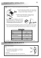
1,00mm² 1,50mm²
1,50mm²
20m. 50m. 100m.
+,
CV, CV
P+, P-
12Vc.a.
+P+ P-
P+P-CV CV
12Vc.c.
+
_
SEC
PRI
~~
230Vc.a.
_
_
C NO
+P+ P-
_
+P+ P-
_
+P+ P-
_
JP2
JP2JP2JP2JP2
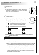
onnection to (2 apartments).
C
IMPORTANT: Configure the JP2 jumper for one or two apartments (see page 33 for the door panel and page 37 for the telephone).
*
+P+ P-
P+P-CV CV
12Vc.c.
+
_
SEC
PRI
~~
230Vc.a.
_
C NO
+P+ P-
_
+P+ P-
_
+P+ P-
_
JP2
JP2JP2JP2JP2
Apartment 2 Apartment 1
Call push button:
Call to apartment 2.
Call to apartment 1.
(1)
Call push button:
Call to apartment 1.
Call to apartment 1.
(1)
Apartment 1
1,50mm²
P+P-CV CVC NO
SAR-12/24
IN IN
NC NA C
PRI
~~ ~~
SEC
TF-104
230Vc.a.
P+P-CV CVC NO
ections chart.
S
Terminal
Distance up to
onnection of an a.c. lock release by using TF-104 transformer
C
and SAR-12/24 relay.
TF-104
SEC
PRI
~~~~
230Va.c.
12Va.c.
P+P-CV CVC NO P+P-CV CVC NO
onnection of an auxiliary device or control for gate automation.
C
-Use an external relay for devices with higher consumption than 12Vd.c. / 1A.
C and NO c .-' ' ' ' ontact free auxiliary
Auxiliary device Control for gate automation
PES-1220
FA-133
T-1772VDT-1772VDT-1772VDT-1772VD
PES-1220
FA-133
T-1772VDT-1772VDT-1772VDT-1772VD
(1)
(1)
PES-1220
PES-1220
PES-1220
1 2
1 2
1 2