
Operation Manual


29
INDEX
Introduction...........................................29
Index.....................................................29
Starting recommendations.......................29
System characteristics..............................30
System operation....................................30
Door panel PES-1220.................................
Description..........................................31
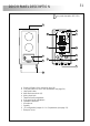
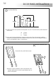
Location......................................32 to 33
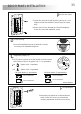
Wiring.................................................33
JP2 configuration jumper.......................33
Final adjustements................................33
Push button label..................................34
Close the door panel.............................34
Power supply FA-133...................................
Installation ..........................................35
Characteristics.....................................35
Lock release installation...........................35
T-1772VD telephone...................................
Description..........................................36
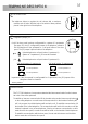
Function push buttons...........................36
Call volume control ..............................37
JP2 configuration jumper.......................37
Intercom function .................................37
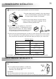
Fix the telephone ..................................38
Installation diagram....................................
Connection to (1 apartment)..................39
Connection to (2 apartments).................39
Sections chart ......................................40
Connection a.c. lock release..................40
Connection auxiliary device...................40
Troubleshooting hints ..............................41
Notes....................................................42
Connection terminals............................36
STARTING RECOMMENDATIONS
O Do not use excessive force when tightening the power supply connection block screws.
O Install the equipment without the power connected.
O Before connecting the system, check the connections between door panel, telephone/s and the
power supply connection.
O Only use compatible T-1772VD telephone.
O Only use parallel or twisted cable (to sections see page 40).
O Do not use single wire.
O Do not double the cable to increase the section.
O The entire installation must be at least 40 cm. away from any other installation otherwise there is
a risk that the audio signal be exposed to interference, or that the system does not work correctly.
O Always use 12 Vd.c. lock releases (cod. 20600149, not included in the kit).
O Do not switch voltage higher than 12 Vd.c. / 1A between C and NO door panel terminals.
O Do always follow the enclosed information.
INTRODUCTION
First of all we would like to thank and congratulate you for the purchase of this product manufactured
by Golmar.
The commitment to reach the satisfaction of our customers is stated through the ISO-9001 certification
and for the manufacturing of products like this one.
Its advanced technology and exacting quality control will do that customers and users enjoy with the
legion of features this system offers. To obtain the maximum profit of these features and a properly
wired installation, we kindly recommend you to expend a few minutes of your time to read this manual.
30
SYSTEM OPERATION
O Audio door entry system with simplified installation (polarised 2 wire bus).
O Up to 1 access door panel.
O Up to 2 apartments (Necessary setting configuration, see page 33 & 37 for door panel & telephone).
O Up to 4 telephones per installation.
O Installations with one apartment, maximum 4 telephones.
O Installations with two apartments, maximum 2 telephones per apartment.
O 'Long' acoustic call acknowledgment signals.
O 'Short' acoustic system busy signals (intercommunication).
O Maximum distance between the door panel and the last telephone: 100m.
O Maximum distance between power supply and telephone: 20m.
O Maximum distance between the door panel and lock release: 20m.
O Door opening timed at 3 seconds.
O D.C. lock release.
O Contact free auxiliary for activating auxiliary devices, do not switch voltage and current higher than
12Vcc/1A between C and NO door panel terminals.
O T-1772VD telephone:
wPrivacy on audio communications.
wIntercommunication function.
wActivation auxiliary device function.
wThree-position control for call volume: maximum, medium and off.
wDifferent call tones which identify the call procedure: door panel and intercom.
O To make a call, the visitor should press over one of the push button ends, (if the door panel is configured
for 2 apartments, each side of push button will call to an apartment) as it is shown on the label of the
push button. An acoustic 'long' tone will be heard confirming the call is in progress once the push button
has been pressed. At this moment, the call will be received at the telephone(s) in the apartment.
O If the door panel is configured for 2 apartments, the visitor can correct his call by pressing a push button
corresponding to a different apartment, in wich case the original call is cancelled.
O The call tone lasts for 40 seconds.
O To establish communication pick up the telephone handset.
O The communication will last for 90 seconds or until the handset is replaced.
O To open the door, press the door release push button during communication process: with one
press, the door release operates during 3 seconds.
During activation, the audio will disappear with the door panel.
O The description of the function push buttons is shown on page 36.
SYSTEM CHARACTERISTICS