
Operation Manual


33
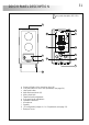
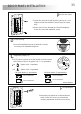
DOOR PANEL INSTALLATION
lace the door panel.
P
Face the door panel to the wall by placing the top at 1,65m.
height and insert the installation wires through the cables
entry.
Drill two holes of 6mm. diameter and insert the wallplugs.
Fix the door panel with especified screws.
oor panel wiring.
D
Connect the installation wires to the terminal connector,
according to the installation diagrams.
inal adjustments.
F
If after starting the system it's considered that the
audio volume isnt correct, proceed with the
necessary adjustments as shown on the picture.
'
34
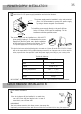
ush button label.
P
Text
Text
To costomize the push button label, insert a flat screwdriver to accede to the label, remove
the push button front cover, see picture A & B . The label is now accesible to mark a text,
see picture C .
Replace the push button front cover, making a light pressure until listenning a click in both
sides of the front cover, see picture D .
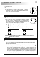
lose the door panel.
C
Finish the door panel assembly by replacing the
aluminium front.
With help of a plain screwdriver,
as shown on the picture.
f
with especified screws,
ix the aluminium front
Text
DOOR PANEL INSTALLATION
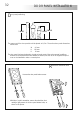
onfiguration jumper 'JP2'.
c
The JP2 jumper is placed on the low left side of the door panel
and it allows to select if the system is for 1 or 2 apartments.
System call to 1 apartment.
System call to 2 apartments.
JP2
JP2
*Factory default
Call push button (1 apartment):
Call to apartment 1.
Call to apartment 1.
Call push button (2 apartments):
Call to apartment 2.
Call to apartment 1.
JP2
1 2
1 2
A B D
C
1
user
2 users
1 user
2
users
1 user
2
users