
Operation Manual


35
POWER SUPPLY INSTALLATION
LOCK RELEASE INSTALLATION
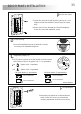
ock release installation.
L
If the lock release will be installed in a metal door,
use a Ø3,5mm. drill and tap the hole In case of
wood door, use a Ø3mm. drill
.
.
IMPORTANT:
The lock release must be 12V direct current, (see page 39).
Optionally lock release 12Vac with TF104 transformer and SAR-12/24 relay (see page 40).
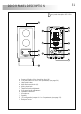
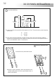
etail of the FA-133 power supply installation and technical features.
D
DIN 46277
Input
Power
Output
Working temperature
Dimensions
Weight
230 Vac / 50 Hz
9 VA
18 Vdc 0,5A
-10ºC ~ + 35ºC
54(W) x 83(H) x 58(D) mm.
400 gr.
Technical features
IMPORTANT: Replace the protection cover once the input terminals have been wired.
36
.
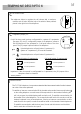
D
escription of the T-1772VD telephone
.
F
unction push buttons
a
d
c
e
b
g
e
a.
b.
c.
d.
e.
f.
g.
h.
i.
Telephone handset
Speaker grille
Microphone hole
hole
Telephone cord connectors
release push button/
Hook switch
Intercommunication push button
Volume control
.
.
.
Subjection .
.
Door .
.
.
.
aux. function
f
h
i
TELEPHONE DESCRIPTION
With the handset picked up, without call reception or during a process
of communication, a pulsation of 1 second activates the lock release
or a pulsation of 3 seconds activates the auxiliary output.
T
erminal connector description
With the handset picked up allows to establish an intercommunication
between two points of the same apartment.
Positive terminal, communication bus.
Negative terminal, communication bus.
Positive.
Negative.
P+:
P - :
+ :
- :
T-1772VD:
P+ P- +
-
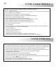
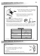
This device has been exclusively designed to be used on Golmar Kit audio AS-1220 SII. Golmar
will not be responsible of the possible damage caused for an improper use or when used for
other purposes than the specified. Install the power supply according to your country rules.
The power supply can be installed on a DIN 46277
guide simply pressing it To disassemble the power
supply from the DIN guide, use a plain screwdriver
to lever the flange as shown on the picture
.
. The FA-
133 power supply uses 3 units over DIN guide.
To install the power supply directly on the wall, drill two
holes of Ø6mm. and insert the wallplugs Fix the
transformer with the specified screws
.
.
The power supply must be installed in a dry and protected
place It's recommended to protect the power supply
by using a thermo-magnetic circuit breaker
.
.
M 4 x 8
3,5 x 25
DIN-7972
DIN-963
3,5 x 25
DIN-7971
3,5 x 25
DIN-7971