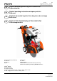
® FS175 DE Original-Bedienungsanleitung und Ersatzteilliste Fugenschneider GB Original operating instruction and spare parts list Floor saw FR Originale du mode d’emploi et liste des pièces de rechange Scie de sol NL Origineel Gebruiksaanwijzing en Reservedelenlijst Vloerenzaagmachine ZN der Bedienungsanleitung: Erstellt am: Erstellt von: Datei: 5007287-01 07 / 2016 Sabrina Linden K:\KDV\5007xxx\5007287-Bedienungsanleitung\ 5007287-01-Bedienungsanleitung-DE-GB-FR-NL.
® FS175 Alle Rechte nach DIN ISO 16016 vorbehalten. Kein Teil dieses Dokuments (Bedienungsanleitung und Ersatzteilliste) darf ohne vorherige schriftliche Genehmigung durch die Onder voorbehoud van alle rechten volgens DIN ISO 16016.
® FS175 EG-KONFORMITÄTSERKLÄRUNG Die Firma EC-DECLARATION OF CONFORMITY DECLARATION DE CONFORMITE DE LA CE Manufacturer EG-KONFORMITEITSVERKARING La Société De Firma ® GÖLZ GmbH Dommersbach 51, D-53940 Hellenthal Tel.
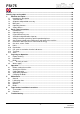
® FS175 Preface ............................................................................................................................................. 22 Warning signs and symbols ........................................................................................................... 22 1. Machine description ............................................................................................................ 23 1.1 Intended use-description ................................................
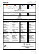
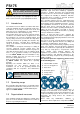
® FS175 Blade shaft speed 2300 rpm Feed Wear dust protection! Wear ear muffs! Important advice! General danger! Never touch! Danger exists to cut oneself! Machine description 1.1 Intended use-description 1.2 Technical data 165 mm - 6.5 in. Max. blade-Ø 450 mm - 17.7 in. Flange size Ø 100 mm - 3.9 in. Engine Max. cutting speed with blade Engine shaft speed Cutting depth gauge Scale on frame Water supply 30l Water tank for dry cutting blades V-belt tension manual 1.3 • • • • approx.
® FS175 11 8 1.5 10 Operating elements 7 6 1 9 1 4 2 3 2 1. Hand wheel - raising and lowering 2. Depth control 5 1.6 The base frame (1+2) is the basis for the floor saw. All other components are built on the base frame. By means of the convenient cutting depth setting (3), the operator can read, at any time, the cutting depth. The rib drive is protected by a poly-V belt guard (4). Thus, the risk of injury is reduced by the rib drive.
® FS175 Attention: Contains instructions which must be strictly observed to prevent damage from the unit and the operator! Important text passages are highlighted in italics or bold or can be found in a grey highlighted text field. 2.1 Intended use The machine has been built in accordance with stateof-the-art standards and the recognized safety rules.
® FS175 GmbH prior approval! This also applies to the installation and adjustment of safety devices as well as to welding and cutting work on supporting structures. Damaged or worn parts of the product must be replaced immediately. Use genuine spare parts only. All spare parts and tools must comply with the technical requirements specified by the manufacturer/ distributor.
® FS175 2.6 Special work related to the maintenance and repair of the machine Observe the adjustment, maintenance and inspection activities and intervals set out in the operating instructions, including information on the replacement of parts and equipment! These activities may be executed by skilled personnel only. Brief operating personnel before beginning special operations or maintenance work, and appoint a person to supervise the activities.
® FS175 Protective installations with fault-current protection units used in non-stationary equipment must be checked for correct operation at least once a month by a properly instructed person. Fault-current and fault-voltage protection units must be checked for correct operation by actuating the testing facility: • once on every working day in the case of mobile equipment, • at least once every six months in the case of stationary equipment. 2.
® FS175 3.2 Attention: Check that all parts of the machine are well fastened before transporting. Before transporting the blade must be removed! For loading, only use lifting gear and tackle of sufficient capacity. Lift the machine using the lifting eye. Place the machine on an even, firm and stable ground. Have the working area well lightened. Keep the working area clean, cluttered areas invite injuries. Operating the machine on enclosed premises, make sure that there is sufficient ventilation.
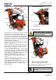
® FS175 3.3.1 Mounting the blade • Blade mounting: • Mount the blade to the manufacturer’s odds (Observe the min. flange-Ø; use only original screws or nuts). • Use only blade diameters which are allowed by the manufacturer. Information: Clean all fastening devices of the blade (flanges, thread of the blade shaft, screws and nuts) before mounting the blade! 1 • Secure the blade and outer flange with fixing nut SW30/SW32. Fit the blade guard again and secure it with screws.
® FS175 valve (1) is closed (ball valve lever in 90°-position to the water flow). For cutting open the ball valve (1) (ball valve lever in the water flow position). 4. Danger: The sound pressure may exceed 85 dB(A)! Appropriate to the application of the machine it could be necessary to wear further protective equipment. Operation Danger: Down coming parts at the building site can cause injuries to the operator! The working area is reserved only for the operator.
® FS175 Completely raise the machine until the brake engages (blade may have no ground contact). Engine switch is in ON position (1). Emergency switch is unlock (2).Start the engine as described in the engines manual (3). 4.3 1 Cutting operation Danger: Some parts of the combustion engine become very hot during operation, risk of burns! Danger: Operating with too high feed the machine might rise out of cut! In emergency situations cut off the engine as described in the engines manual! 1 4.
® clean Flange and blade holder Poly-V belt Water nozzle and feeding hoses clean If damaged Yearly X check X 5.4 X replace X X X clean 5.5 X X Lubricating chart Poly-V belt Unscrew the screws that fix the motor (4x M10x30, DIN EN ISO 4017) and the screw that fixes the eccentric. Move the motor forwards by turning the eccentric counter clockwise. In this position the poly-V belt can be replaced easily. Stress the poly-V belt by turning eccentric clockwise.
® FS175 6.2 Removal Problem Slacken all screws. Depending on the size of the bush remove one or two. After oiling point and thread of grub screws or under head and thread of cap screws, insert them into the jacking off holie(s) in bush. Tighten screw (s) uniformly and alter neatly until the bush is loose in the hub and pulley is free on the shaft. Remove pulley bush assembly from shaft.