
User manual


14
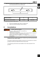
3. MarkthemountingholespacingXandgrommetYbyusingthe
mountingbracketandasuitablepen.
Fig . 10: Wall mounting
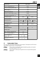
Article number X Y
44529, 44530, 44531, 44532 120 mm Ø8,5mm
Ta b . 4 : MountingholespacingXandgrommetY
4. Drill the mounting holes with a suitable tool.
5. AttachtheLEDoodlightmotionsensor.
6 Installation
Risk of electric shock
• LetopencableendsONLYassembleby
experiencedelectrician.
• Cutoffpowersupplybeforeanyworkontheproduct,switchoff
safetyfuseandsecureagainstreconnection.
• Assureandchecktheabsenceofvoltagebeforeanyworkon
theproduct.
Modelswithoutamatedprotectivecontactplugmustbepermanently
installedonthepowersupply.
Thepowercablesusedmusthaveaminimumcross-sectionof1.0mm².
Strandsmustbeprovidedwithwireendferrules.
The following connections are made at the luster terminal of the
product: