
Installation Guide


ON
OFF
ON
OFF
ON
OFF
ON
OFF
ON
OFF
ON
OFF
ON
OFF
ON
OFF
ON
OFF
ON
OFF
ON
OFF
ON
OFF
ON
OFF
ON
OFF
2
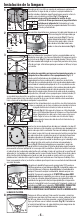
Preparation
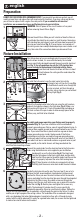
DO NOT USE THIS FIXTURE WITH A DIMMING CIRCUIT. If you presently have dimmer controls, you will
need to remove them, and replace them with regular electrical switches. If you have a three way dimmer,
you will have to replace it with a regular three way switch. If you are unfamiliar with electrical
installations, we recommend you have a qualified electrician do your installation.
Remove the old fixture. Make yourself a sketch of how the fixture is
wired (index the sketch by wire color) or mark the wires themselves
with masking tape and a pencil so you will know how to connect the
wires to your new fixture (Fig. 2). If several wires are involved or if
the wiring seems more complicated and perhaps even includes a red
wire, take note of the connections before you disconnect them.
1
OFF
WARNING: Shut off power at the circuit breaker or fuse panel
before removing the old fixture (Fig. 1).
english
Fig. 1
Fig. 2
Fixture Installation
Fig. 4
Fig. 2
Fig. 3
1
2
3
6
5
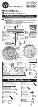
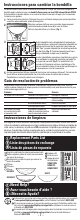
To install the bulb socket, snap the metal socket clip into the
rectangular hole until you feel it snap (Fig.
2). Feed the bulb socket wires through the
circular wire hole, pull them through on
the other side as much as you can without
pulling it tight (Fig. 3).
4
Attach the threaded center tube to the pan using the split washers,
and nuts (included) as shown in the illustration (Fig. 4). Make sure
that you have 3/8 inches to 1/2 inch of threaded tube protruding on
the back surface of the pan in order to allow enough space for the
diffuser, cap, and finial to be attached.
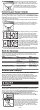
Locate the key hole slots on the pan. The inner two (2) are set at a
distance that will accommodate a standard electrical box mount.
Position the fixture pan over the electrical box so that the machine
screws protruding from the electrical box pass through the elongated
keyholes in the fixture's pan. Once both screws are through the
keyholes, twist the pan, until both screws are up against the smaller
end of the slot (Fig. 8). Hold in place and tighten the screws very
tightly. The hardware kit includes two (2) screws specifically
designed to ground the fixture to a metal electrical box. Tighten the
screws until the underside of the screwhead is cutting through the paint on the fixture's surface
and the pan is tight up against the ceiling surface. The underside of the screwhead is designed
with a serrated edge, that when tightened against a painted surface will cut through to make
contact with the metal underneath. In order for a ground to be made, the screws must be tightened
to make a bare metal to bare metal contact.
3/8 in.
1 cm
Fig. 1
This fixture does not use a mounting bracket to secure it to the
electrical box. Instead, it is secured to the box by the included
screws specifically designed to ground the pan to a metal electrical
box (Fig. 1). For safe operation, use only the 1-1/2 electrical box
screws included in the hardware kit included with the fixture.
Screw them into the electrical box until there is about
3/8 inch between the ceiling and the underside of the
screw head.
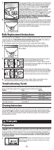
For safety and proper operation, your fixture must be properly
grounded (Fig. 5). If you are unfamiliar with the methods of
properly grounding your fixture, consult a qualified electrician. A
green or bare copper ground wire is pre-attached to your fixture
pan. If your electrical box is plastic and has a green or bare
copper grounding wire inside, the bare end of the fixture
grounding wire must be secured to the green grounding wire
inside your electrical box using the small wire nut (included). If
your electrical box is metal and contains no ground wire as part
of a grounded electrical system, see #6, as the metal chassis will be grounded via the
electrical box mounting screws.
Connect the supply leads from the electrical box to the fixture wire
leads using the medium wire nuts supplied in your installation
hardware kit as per the illustration (Fig. 6). The black lead
from the fixture goes to the black supply lead, and the white
lead from the fixture goes to the white supply lead. Secure the
wire nuts properly to prevent the wires from coming loose
(Fig. 7). Tape the wire nuts to the wire using electrical tape.
Carefully push the excess wires back inside the electrical box.
Fig. 6
Fig. 7
Fig. 8
Fig. 8
Fig. 5
- 2 -