® C IO-230F US INSTALLATION & OPERATING INSTRUCTIONS FOR ARUF, ARPF, ARPT and AEPT SERIES AIR HANDLER Made in the USA by: Goodman Manufacturing Company, L.P. 2550 North Loop West, Suite 400 - Houston, Texas 77092 www.goodmanmfg.com or www.amana-hac.com © 2003-2004 Goodman Manufacturing Company, L.P.
INDEX IMPORTANT SAFETY INSTRUCTIONS Recognize Safety Symbols, Words, and Labels The following symbols and labels are used throughout this manual to indicate immediate or potential hazards. It is the owner’s responsibility to read and comply with all safety information and instructions accompanying these symbols. Failure to heed safety information increases the risk of serious personal injury or death, property damage and/or product damage. INTRODUCTION .....................................................
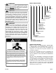
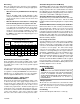
MODEL IDENTIFICATION WARNING AR THIS PRODUCT IS FACTORY SHIPPED FOR USE WITH A 208-230/1/60 ELECTRICAL POWER SUPPLY. THIS AIR HANDLER MUST NOT BE RECONFIGURED TO OPERATE WITH ANY OTHER POWER SUPPLY. U F 024 00 A 1 A Revision WARNING Electrical Supply 208 - 230/1/60 WHEN INSTALLING OR SERVICING THIS EQUIPMENT, SAFETY CLOTHING, INCLUDING HAND AND EYE PROTECTION, IS STRONGLY ADVISED. IF INSTALLING THIS EQUIPMENT IN AN AREA THAT HAS SPECIAL SAFETY REQUIREMENTS (HARD HATS ETC.
When matched with a Goodman or Amana brand condenser or heat pump, an ARI certified rating is available for many combinations. 600 800 1000 1200 1400 1600 1800 2000 The AEPT models are equipped with an ECMTM motor. An ECMTM motor is more efficient than a standard PSC motor and offers features such as soft-start, controlled off-delays, and constant CFM. Additional features and the associated controls are discussed later in this manual. Electric heat is available for all models.
maximum heat and allow the system to reach steady state conditions. Insert two thermometers, one in the return air and one in the supply air. The temperature rise is the supply air temperature minus the room air temperature. require external filtering. A washable filter is available as an accessory. To ensure optimum performance frequent filtercleaning isadvised.RefertoTable 5 for the appropriate filter. Use HKR specification sheets to determine the HKR available for a given air handler.
Wire Sizing Wire size is important to the operation of your equipment. Use the following check list when selecting the appropriate wire size for your unit. • Air Handler Only (Non-Heat Kit Models) The building supply connects to the stripped black and white wires contained in the air handler electrical compartment cavity. A ground screw is also contained in this area.
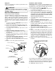
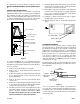
Piping Size For the correct tubing size, follow the specification for the condenser/heat pump. TXV Models (ARPT and AEPT) IMPORTANT NOTE: In order to prevent damage to the sensing bulb, it is not permanently installed in the factory. This bulb is to be removed prior to brazing. Place in proper location after braze joint has cooled (Figure 3). 1. Loosen the 13/16 nut 1 TURN ONLY. No pressure loss indicates possible leak. 2. Remove the nut and discard the black or brass cap. 3.
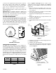
Refer to Figures 5 through 7 for the location of the components referenced in the following steps. Figure 5 illustrates the new installation location for the removed components. 1. Before inverting the air handler, remove all access panels, the coil rear channel bracket, and the filter close-off panel. 2. Remove the evaporator coil and the horizontal drain pan. Discard horizontal drain pan. 3. Install the provided plastic plug into the vacated access panel. 4.
To complete the conversion, slide the evaporator coil into thechassisandattachthe three (3)accesspanels.(Figure 7). 7. Install the plastic plug removed in step 5 to the right side lower access panel and the oval shaped rubber gasket to the lower left access panel. CONVERSION TO HORIZONTAL The “B” series product is not suitable for horizontal application and must not be used for this type of installation. The following describes converting to “Horizontal LeftHand”.
IMPORTANT NOTE: THE EVAPORATOR COIL IS COATED WITH OILS THAT MAY DISSOLVE STYROFOAM AND CERTAIN TYPES OF PLASTICS. THEREFORE, A REMOVAL PUMP OR FLOAT SWITCH MUST NOT CONTAIN ANY OF THESE MATERIALS. Dipswitch Functions The AEPT air handler motor has an electronic control that contains an eight (8) position dip switch. The function of these dipswitches are shown in Table 9.
Humidity Control When using a Humidistat (normally closed), cut jumper PJ6 on the control board. The Humidistat will only affect cooling airflow by adjusting the Airflow to 85%. Two Stage Heating When using staged electric heat, cut jumper PJ4 on the control board. Thermostat Wiring Use thermostat wiring diagram Figures 10 thru 13 and those provided with the thermostat when making these connections. NOTE: DO NOT USE THESE DIAGRAMS FOR AEPT MODELS.
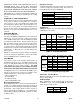
FIGURE 12 AR/ARUF/ARPF/ARPT 18-60 10 KW & BELOW TYPICAL H/P ROOM THERMOSTAT HEAT PUMP C B L U E W2 O Y R O R A N G E W H I T E Y E L L O W Y O C W2 #18 GA. 7 WIRE AR UNIT G R E R E D R Y O SEE NOTE #3 W BL R R RED G G GREEN BR W W WHITE BL BL BLUE #18 GA. 5 WIRE (OPTIONAL) OUTDOOR THERMOSTAT CLOSE ON TEMPERATURE FALL #18 GA.
THERMOSTATS Note: Second Stage heat can be accomplished by multistage heating thermostat or the addition of an outdoor thermostat as shown in Figures 12 and 13. • • • Goodman part number CHT18-60 is a single-stage cool and single-stage heat thermostat. • Goodman part number HPT18-60 is a single-stage cool, two-stage heat pump thermostat. The first stage is heat pump heating and the second stage is optional electric heat.