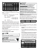
ATUF/ARUF/ARPF/ADPF/ASPF AIR HANDLERS INSTALLATION & OPERATING INSTRUCTIONS ® C US NOTE: ATUF models are suitable for Upflow and Horizontal Installations only. Do not use for Downflow Installations RECOGNIZE THIS SYMBOL AS A SAFETY PRECAUTION. ATTENTION INSTALLING PERSONNEL Prior to installation, thoroughly familiarize yourself with this Installation Manual. Observe all safety warnings. During installation or repair, caution is to be observed.
CONTENTS Important Safety Instructions ............................................. 2 Important Note to Owner Regarding Product Warranty ..... 3 Shipping Inspection ........................................................... 3 Codes & Regulations ........................................................ 3 Replacement Parts ............................................................ 3 Pre-Installation Instructions ............................................... 3 Location ...................................
Product limited warranty certificates for models currently in production can be viewed at www.goodmanmfg.com or www.amana-hac.com. If your model is not currently in production or does not appear on the website, please contact your installing contractor or contact customer service (877254-4729) to obtain a copy of your warranty certificate.
return air filter grille. Air handlers mounted in the downflow orientation, including “B” series, require external filtering. A washable filter is available as an accessory. To ensure optimum performance frequent filter cleaning is advised. Refer to Table 1 for the appropriate filter. Pre-Installation Instructions Carefully read all instructions for the installation prior to installing product.
CFM 600 800 1000 1200 1400 1600 1800 2000 3 5 16 12 10 8 7 6 5 5 25 19 15 13 11 9 8 8 HEAT KIT NOMINAL kW 6 8 10 15 20 32 24 19 16 14 12 11 10 37 38 22 19 16 14 12 11 38 30 25 22 19 17 15 46 38 33 28 25 23 51 43 38 34 30 21 HIGH VOLTAGE! To avoid property damage, personal injury or death due to electrical shock, this unit MUST have an uninterrupted, unbroken electrical ground.
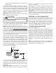
Maximum Overcurrent Protection (MOP) Every installation must include an NEC (USA) or CEC (Canada) approved overcurrent protection device. Also, check with local or state codes for any special regional requirements. Protection can be in the form of fusing or HACR style circuit breakers. The Series and Rating Plate can be used as a guide for selecting the MAXIMUM overcurrent device. Refrigerant Lines This product is factory-shipped under pressure. Follow these instructions to prevent injury.
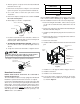
2. After the gas has escaped, remove the nut and discard the black or brass cap. ARUF, ATUF or ARPF Model Insulation Kit 3. Remove the check piston to verify it is correct and then replace the piston. See piston kit chart in instructions. 1729 / 1824 DPI18-30/20 3030 / 1931 / 3636 DPI36-42/20 3642 / 3743 / 4860 / 4961 DPI48-61/20 4. Use a tube cutter to remove the spin closure on the suction line. Table 7 5. Remove the tailpiece clamped to the exterior and slide the 13/16 nut into place.
final location (See Figure 6). 3” FLAT INSULATION RETAINER (BOTH SIDES) DPIH KIT SECONDARY DRAIN PRIMARY DRAIN Figure 4 To complete the conversion, slide the evaporator coil into the chassis and attach the three (3) access panels. (Figure 5). Figure 6 1. Remove the (3) air handler access panels. 2. Remove the “J” shaped bracket that retains the evaporator coil. WRAPPER 3. Remove the flowrator from the lower left side access panel and slide out the evaporator coil and horizontal drain pan.
drain line located inside the building. Use Armaflex® or similar material. A Secondary Condensate Drain Connection has been provided for areas where the building codes require it. Pitch the drain line 1/4" per foot to provide free drainage. Insulate drain lines located inside the building to prevent sweating. Install a condensate trap to ensure proper drainage. If the secondary drain line is required, run the line separately from the primary drain and end it where it can be easily seen.
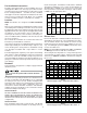
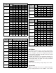
CFM deliverd against External Static Pressure Model ARUF172916 ARUF182416 ARUF193116 ARUF303016 ARUF363616 Speed 0.2" 0.3" 0.4" 0.5" 1155 1090 1025 950 895 Med. 940 890 860 815 755 Low 695 665 650 610 550 High 1155 1090 1025 950 895 Low 695 665 650 610 550 Med. 940 890 860 815 755 High 1,700 1,660 1,625 1,545 1,505 1,345 ARUF486016 ARUF496116 Speed ADPF18241/16 ARPF36421* ARPF37431* ARPF48601* ARPF49611* 0.5" 895 Med.
thermostat as shown in Figures 10 and 11. Goodman® part number CHT18-60 is a single-stage cool and single-stage heat thermostat. Goodman® part number HPT18-60 is a single-stage cool, two-stage heat pump thermostat. The first stage is heat pump heating and the second stage is optional electric heat. If additional features are desired, such as digital or programmable capabilities, these thermostats are commercially available. Follow the thermostat manufacturer’s instruction for installation.
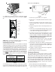
WARNING HIGH VOLTAGE! DISCONNECT ALL POWER BEFORE SERVICING. MULTIPLE POWER SOURCES MAY BE PRESENT. FAILURE TO DO SO MAY CAUSE PROPERTY DAMAGE, PERSONAL INJURY OR DEATH. ROOM THERMOSTAT W Y G #18 GA. 4 WIRES WITH COOLING 3 WIRES WITHOUT R AT/AR UNIT R G W RED GREEN WHITE Y CONTACTOR TO CONDENSING COIL UNIT 24V. CONNECTIONS BLUE #18 GA. 2 WIRES Figure 8 - Low Voltage Wiring Diagram for Cooling Unit with optional heat kit 10kW and below AT/AR UNIT W2 #18 GA.
WARNING HIGH VOLTAGE! DISCONNECT ALL POWER BEFORE SERVICING. MULTIPLE POWER SOURCES MAY BE PRESENT. FAILURE TO DO SO MAY CAUSE PROPERTY DAMAGE, PERSONAL INJURY OR DEATH. FIGURE 10 ATUF/ARUF/ARPF/ADPF 18-60 10 KW & BELOW TYPICAL H/P ROOM THERMOSTAT HEAT PUMP C W2 O Y R B Y O C W2 #18 GA. 7 WIRE AT/AR UNIT G R E R R I R Y R R RED G G GREEN BR W W WHITE BL BL BLUE O NOTE W BL #18 GA. 5 WIRE (OPTIONAL) OUTDOOR THERMOSTAT CLOSE ON TEMPERATURE FALL #18 GA.
ASPF THERMOSTAT CONNECTIONS The following composite wiring diagrams detail various configurations in which the ASPF air handlers can be used. Examples include single-stage cooling and heat pump with single or two-stage electric heating. All these configurations can be applied with convenient connections to outdoor thermostat applications. The following sections will be detailed: • Single-Stage Cooling (GMC Thermostat Part #CHT18-60 or equivalent.
WARNING HIGH VOLTAGE! DISCONNECT ALL POWER BEFORE SERVICING. MULTIPLE POWER SOURCES MAY BE PRESENT. FAILURE TO DO SO MAY CAUSE PROPERTY DAMAGE, PERSONAL INJURY OR DEATH. #18 GA. 5 WIRES WITH COOLING 4 WIRES WITHOUT W W2 Y G R C YL BR RD R GR G WH W1 BR W2 BR YL CONDENSING UNIT 24V CONNECTION BL Y1 YL YL Y2 O BL TB COOLING UNIT WITH OPTIONAL HEAT KITS OF 15 kW AND ABOVE AND ROOM THERMOSTAT WITH TWO STAGES OF HEAT #18 GA.
WARNING HIGH VOLTAGE! DISCONNECT ALL POWER BEFORE SERVICING. MULTIPLE POWER SOURCES MAY BE PRESENT. FAILURE TO DO SO MAY CAUSE PROPERTY DAMAGE, PERSONAL INJURY OR DEATH. #18 GA. 7 WIRE C W2 O Y R Y O C W2 YL OR G R GR E BR C RD RD R RD GR WH G BL YL OR W1 WH WH WH W2 RD WH Y1 OR Y2 BL BL O YL OR OR BR TB HEAT PUMP UNIT WITH OPTIONAL HEAT KITS OF 15 kW AND ABOVE NOTES: 1) OUTDOOR THERMOSTAT (OT-1) SHOULD BE THE FIRST TO CLOSE AND THE LAST TO OPEN.
WARNING HIGH VOLTAGE! DISCONNECT ALL POWER BEFORE SERVICING. MULTIPLE POWER SOURCES MAY BE PRESENT. FAILURE TO DO SO MAY CAUSE PROPERTY DAMAGE, PERSONAL INJURY OR DEATH. NOTE: This is not applicable to ASPF models.
THIS PAGE LEFT INTENTIONALLY BLANK 18
THIS PAGE LEFT INTENTIONALLY BLANK 19
Goodman Manufacturing Company, L.P. 5151 San Felipe, Suite 500, Houston, TX 77056 www.goodmanmfg.com © 2004-2010 Goodman Manufacturing Company, L.P.