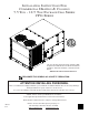
INSTALLATION INSTRUCTIONS FOR COMMERCIAL HEATING & COOLING 7.5 TON - 12.5 TON PACKAGE GAS SERIES CPG SERIES ® C US This Forced Air Central Unit Design Complies With Requirements Embodied in The American National Standard / National Standard of Canada Shown Below. ANSI Z21.47•CSA-2.3 Central Furnaces RECOGNIZE THIS SYMBOL AS A SAFETY PRECAUTION. ATTENTION INSTALLING PERSONNEL Prior to installation, thoroughly familiarize yourself with this Installation Manual. Observe all safety warnings.
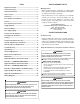
REPLACEMENT PARTS Index Replacement Parts ........................................................ 2 ORDERING PARTS Safety Instructions ........................................................ 2 When reporting shortages or damages, or ordering repair parts, give the complete unit model and serial numbers as stamped on the unit’s nameplate. General Information ...................................................... 3 Unit Location .................................................................
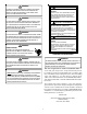
WARNING WARNING THIS PRODUCT CONTAINS OR PRODUCES A CHEMICAL OR CHEMICALS CARBON MONOXIDE POISONING HAZARD WHICH MAY CAUSE SERIOUS ILLNESS OR DEATH AND WHICH ARE KNOWN TO THE STATE OF CALIFORNIA TO CAUSE CANCER, BIRTH FAILURE TO KEEP THIS COMPARTMENT CLOSED EXCEPT WHEN SERVICING COULD RESULT IN CARBON MONOXIDE POISONING OR DEATH. DEFECTS OR OTHER REPRODUCTIVE HARM.
System design and installation should also, where applicable, follow information presented in accepted industry guides such as the ASHRAE Handbooks. The manufacturer assumes no responsibility for equipment installed in violation of any code or regulation. The mechanical installation of the packaged roof top units consists of making final connections between the unit and building services; supply and return duct connections; and drain connections (if required).
GROUND LEVEL INSTALLATIONS ONLY: 3 3/4” • When the unit is installed on the ground adjacent to • the building, a level concrete (or equal) base is recommended. Prepare a base that is 3” larger than the package unit footprint and a minimum of 3” thick. The base should also be located where no runoff of water from higher ground can collect in the unit.
• Curb insulation, cant strips, flashing and general roofing material are furnished by the contractor. The curbs must be supported on parallel sides by roof members. The roof members must not penetrate supply and return duct opening areas as damage to the unit might occur. NOTE: The unit and curb accessories are designed to allow vertical duct installation before unit placement. Duct installation after unit placement is not recommended. CAUTION ALL CURBS LOOK SIMILAR.
Ensure that the top of the duct connection frame is flush with the top of the roof curb. Remove wood struts mounted beneath unit base frame before setting unit on roof curb. These struts are intended to protect unit base frame from fork lift damage. Removal is accomplished by extracting the sheet metal retainers and pulling the struts through the base of the unit. Refer to rigging label on the unit. • Your unit may be equipped with a steel shipping brace located underneath the unit (under compressors).
Important: If using bottom discharge with roof curb, ductwork should be attached to the curb prior to installing the unit. Ductwork dimensions are shown in Roof Curb Installation Instructions. DATA Corner Weight - A CPG Weights (lbs) 090/102 120 150 195 230 335 Corner Weight - B 270 330 390 Refer to the Roof Curb Installation Instructions for proper curb installation. Curbing must be installed in compliance with the National Roofing Contractors Association Manual.
(ANSI-NFPA 70). A ground lug is provided for this purpose. Size grounding conductor in accordance with Table 250-95 of the National Electrical Code. Do not use the ground lug for connecting a neutral conductor. • Connect power wiring to the middle contactor within the main control box. CAUTION CONDUIT AND FITTINGS MUST BE WEATHER‐TIGHT TO PREVENT WATER ENTRY INTO THE BUILDING . FAN FAN RCCF C All line voltage connections must be made through weatherproof fittings.
3 3/4” LEAD Red Green Yellow Purple Blue W hite Brown DIMPLES MARK DRILL LOCATIONS HIGH VOLTAGE ENTRANCE 10 3/16” THERMOSTAT R (24V) G (Fan) Y1 (High Cool) Y2 (Low Cool) Common (if req'd) W 1 (Heat) W 2 (High Heat) LOW VOLTAGE ENTRANCE CPG 090 THROUGH 300 (GAS HEAT) GAS SUPPLY PIPING 26 ½” WARNING ELECTRICAL ENTRANCE LOCATIONS TO PREVENT PERSONAL INJURY OR DEATH DUE TO IMPROPER INSTALLATION, ADJUSTMENT, ALTERATION, SERVICE OR MAINTENANCE, REFER TO THIS MANUAL .
The rating plate is stamped with the model number, type of gas and gas input rating. Make sure the unit is equipped to operate on the type of gas available. The gas line installation must comply with local codes, or in the absence of local codes, with the latest edition of the National Fuel Gas Code NFPA 54/ANSI Z223.1.
PROPANE GAS INSTALLATIONS ROOF TOP LOCATION AND INSTALLATION The gas supply piping location and installation for roof top units must be in accordance with local codes or, in the absence of locals codes, with ordinances of the latest edition of the National Fuel Gas Code (ANSI Z223.1). WARNING TO AVOID PROPERTY DAMAGE, PERSONAL INJURY OR DEATH DUE TO FIRE OR EXPLOSION CAUSED BY A PROPANE GAS LEAK, INSTALL A GAS DETECTING WARNING DEVICE .
6. All pipe connections should be sealed with a pipe thread compound, which is resistant to the fuel used with the furnace. A soapy water solution should be used to check all joints for leaks. A 1/8" NPT plugged tap is located on the entering side of the gas valve for test gauge connection to measure supply (main) gas pressure. Another 1/8" tap is provided on the side of the manifold for checking manifold pressure.
CONTRACTOR RESPONSIBILITY WARNING The installing contractor must be certain that: MOVING MACHINERY HAZARD! TO PREVENT POSSIBLE PERSONAL INJURY OR DEATH, DISCONNECT POWER TO THE UNIT AND PADLOCK IN THE “OFF” POSITION BEFORE SERVICING FANS. • • HEATING STARTUP • This unit is equipped with an electronic ignition device to automatically light the main burners. It also has a power vent blower to exhaust combustion products.
Three Phase Models 3) PERCENT VOLTAGE UNBALANCE = 100 X TENSION AND ALIGNMENT ADJUSTMENT Correct belt tension is very important to the life of your belt. Too loose a belt will shorten its life; too tight, premature motor and bearing failure will occur. Check you belt drive for adequate “run-in” belt tension by measuring the force required to deflect the belt at the midpoint of the span length. Belt tension force can be measured using a belt tension gauge, available through most belt drive manufacturers.
Secondary Limit Control EVAPORATOR FAN ROTATION CHECK (THREE PHASE MODELS ONLY) The secondary limit control is located on the top of the blower scroll assembly. This control opens when elevated temperatures are sensed. Elevated temperatures at the control are normally caused by blower failure. The reason for the opening should be determined and repaired prior to resetting.
Main Burner Flame Check INLET GAS PRESSURE NATURAL Min. 5.0" W.C., Max. 10.0" W.C. PROPANE Min. 11.0" W.C., Max. 14.0" W.C. Flames should be stable, soft and blue (dust may cause orange tips but they must not be yellow) and extending directly outward from the burner without curling, floating or lifting off. Temperature Rise Check NOTE: Inlet Gas Pressure Must Not Exceed the Maximum Value Shown.
5. Check supply fan rotation. If the supply fan is rotating in the wrong direction, disconnect and lock off Single Point Power Block. Do not attempt to change load side wiring. Internal wiring is set at the factory to assure that the supply fan and compressors all rotate in the proper direction. Verification of correct supply fan rotation at initial startup will also indicate correct compressor rotation. Reconnect power and check for proper operation. 6.
The pressure regulator on LP gas models is adjusted for 10.0" w.c. manifold pressure and is intended to prevent over-firing only. Do not attempt adjustment of the built-in pressure regulator unless the supply pressure is at least 7.0" w.c. on natural gas or 14.0" w.c. on propane gas. Check the location of the ignition electrode and the flame sensor for correct gap setting.
The diagnostic fault code is 1 flash for a lockout due to failed ignition attempts or flame dropouts. The integrated control will automatically reset after one hour, or it can be reset by removing the thermostat signal or disconnecting the electrical power supply for over five seconds.
Open Thermal Protection Device After adjustment the furnace temperature rise must be within the range specified on the unit data plate. NOTE: Thermal efficiency of the furnace is a product efficiency rating determined under continuous operating conditions independent of any installed system. If the primary limit switch opens, the gas valve is immediately deenergized, the induced draft and air circulating blowers are energized.
Preventive maintenance is the best way to avoid unnecessary expense and inconvenience. Have this system inspected at regular intervals by qualified service personnel, at least twice a year. Routine maintenance should cover the following items: VL & VM SHEAVES ADJUSTMENT 1. Loosen set screw “B” using a 5/32" Allen key. 2. Making half or full turns from closed position, adjust sheave pitch diameter for desired speed. DO NOT OPEN MORE THAN FIVE FULL TURNS. 3. Tighten set screw “B” securely over flat. 4.
Flames should be stable, soft and blue (dust may cause orange tips but must not be yellow). The flames must extend directly outward from the burner without curling, floating or lifting off. CLEAN OUTSIDE COIL (QUALIFIED SERVICER ONLY) The coil with the outside air flowing over it should be inspected annually and cleaned as frequently as necessary to keep the finned areas free of lint, hair and debris.
APPENDIX A BLOWER PERFORMANCE DATA BELT DRIVE - STANDARD HORIZONTAL CPG090 STANDARD BELT DRIVE HORIZONTAL TURNS OPEN ESP, In H2 O 0 CFM RPM BHP 1 2 3 4 CFM RPM BHP CFM RPM BHP CFM RPM BHP CFM RPM BHP CFM RPM 3381 703 0.99 3078 659 0.78 1.02 0.86 2946 703 0.82 2604 659 0.63 CFM RPM BHP CFM RPM BHP 3231 700 0.96 2928 656 0.75 0.99 0.83 2796 700 0.79 0.1 0.3 0.5 0.7 0.9 1.1 3453 2964 2537 891 896 902 1.5 1.29 1.08 3492 841 1.36 3094 2524 846 852 1.18 0.
APPENDIX A BLOWER PERFORMANCE DATA BELT DRIVE - STANDARD DOWN SHOT CPG090 STANDARD BELT DRIVE DOWN SHOT TURNS OPEN ESP, In H2 O 0 CFM RPM 1 2 3 0.1 RPM 5 BHP CFM RPM BHP 3522 750 1.14 3228 706 0.94 2964 661 0.73 3337 800 1.19 3102 756 1 2800 706 0.76 2504 661 0.59 2834 806 0.99 2603 757 0.8 BHP CFM RPM BHP CFM RPM BHP CFM RPM BHP CFM RPM BHP CFM RPM BHP 2814 658 0.70 0.3 0.5 0.7 0.9 4 BHP CFM RPM BHP CFM RPM BHP CFM RPM BHP CFM 3453 893 1.5 2957 899 1.
APPENDIX A BLOWER PERFORMANCE DATA BELT DRIVE - HIGH STATIC (“AA” MODELS ONLY) CPG090 HIGH STATIC BELT DRIVE DOWN SHOT TURNS OPEN ESP, In H 2O 0 CFM RPM 1 BHP CFM RPM 2 BHP CFM 3 RPM BHP CFM RPM 4 BHP CFM RPM 5 BHP 0.7 0.9 1.1 DO NOT OPERATE 1.3 1.5 1.7 3346 1118 2.24 1.9 2.1 3009 1125 2.05 3616 3275 1063 1069 2.17 2.05 2885 1074 1.97 CFM RPM BHP 3575 904 1.66 3258 925 1.56 3113 909 1.41 2722 915 1.25 3580 1013 1.97 3001 948 1.
APPENDIX B ELECTRICAL DATA ELECTRICAL DATA VOLTAGE VOLTAGE LIMITATION MODELS (NAMEPLATE) MIN MAX 7.5 TON 8.5 TON 10 TON 12.5 TON COMPRESSOR (ea) Qty RLA LRA OD FAN MOTORS (ea) ID MOTOR APPL Qty HP RLA ID FAN MOTOR (ea) HP FLA 208/230-60-3 187 253 2 13.1 83.1 2 1/4 1.40 BD STD STATIC 1.5 5.0 460-60-3 414 506 2 6.1 41.0 2 1/4 0.80 BD STD STATIC 1.5 2.5 575-60-3 518 633 2 4.4 33 2 1/4 0.60 BD STD STATIC 1.5 2.3 208/230-60-3 187 253 2 14.5 98.0 2 1/4 1.
APPENDIX C UNIT DIMENSIONS 7.5 Y 8.5 10 12.5 52 7/8" 52 7/8" 52 7/8" 58 7/8" 99 1/8” Y 61 3/4” 12 5/8” 5 7/8” 28 3/8” 7 3/8” RETURN 13 7/8” 36 3/8” SUPPLY 6 1/2” RETURN 6 1/4” HORIZONTAL DISCHARGE 5 3/8” SUPPLY NOTE For horizontal discharge, remove the supply and return duct covers and place them over the vertical discharge return and supply openings. Install with insulation facing up, using the longer screws provided in the literature package.
CPG(090/102/120/150)2104B*/7B* THREE PHASE 460-575/60 HZ BELT DRIVE WIRING DIAGRAM HIGH VOLTAGE! DISCONNECT ALL POWER BEFORE SERVICING OR INSTALLING THIS UNIT. MULTIPLE POWER SOURCES MAY BE PRESENT. FAILURE TO DO SO MAY CAUSE PROPERTY DAMAGE, PERSONAL INJURY OR DEATH.
CPG(090/102/120/150)2104B*/7B* THREE PHASE 460-575/60 HZ BELT DRIVE WIRING DIAGRAM HIGH VOLTAGE! DISCONNECT ALL POWER BEFORE SERVICING OR INSTALLING THIS UNIT. MULTIPLE POWER SOURCES MAY BE PRESENT. FAILURE TO DO SO MAY CAUSE PROPERTY DAMAGE, PERSONAL INJURY OR DEATH.
CPG(090/102/120/150)2103B* THREE PHASE 208-240/60 HZ BELT DRIVE WIRING DIAGRAM HIGH VOLTAGE! DISCONNECT ALL POWER BEFORE SERVICING OR INSTALLING THIS UNIT. MULTIPLE POWER SOURCES MAY BE PRESENT. FAILURE TO DO SO MAY CAUSE PROPERTY DAMAGE, PERSONAL INJURY OR DEATH.
CPG(090/102/120/150)2103B* THREE PHASE 208-240/60 HZ BELT DRIVE WIRING DIAGRAM HIGH VOLTAGE! DISCONNECT ALL POWER BEFORE SERVICING OR INSTALLING THIS UNIT. MULTIPLE POWER SOURCES MAY BE PRESENT. FAILURE TO DO SO MAY CAUSE PROPERTY DAMAGE, PERSONAL INJURY OR DEATH.