
Manual


12
PROPANE GAS INSTALLATIONS
T
O
AVOID
PROPERTY
DAMAGE
,
PERSONAL
INJURY
OR
DEATH
DUE
TO
FIRE
OR
EXPLOSION
CAUSED
BY
A
PROPANE
GAS
LEA K
,
INSTALL
A
GAS
DETECT ING
WARNING
DEVICE
.S
INCE
RUST
CAN
REDUCE
THE
LEVEL
OF
ODORANT
IN
PROPANE
GAS
,
A
GAS
DETECT ING
WARNING
DEVICE
IS
THE
ONLY
RELIABLE
WAY
TO
DETECT
A
PROPANE
GAS
LEA K
.C
ONTACT
A
LOCAL
PROPANE
GAS
SUPPLIER
ABOUT
INSTALLING
A
GAS
DETECT ING
WARNING
DEVICE
.
WARNING
IMPORTANT NOTE: Propane gas conversion kits must be
installed to convert units to propane gas.
All propane gas equipment must conform to the safety
standards of the National Board of Fire Underwriters (See
NBFU Manual 58). Line pressure 11.3 - 14” w.c.
For satisfactory operation, propane gas manifold pressure
must be within 9.7 - 10.3 inches w.c. for high fire and within
6.7 - 7.3 inches w.c. low fire at the manifold with all gas appli-
ances in operation. Maintaining proper gas pressure depends
on three main factors:
1. Vaporization rate, which depends on (a) temperature
of the liquid, and (b) wetted surface area of the
container or containers.
2. Proper pressure regulation.
3. Pressure drop in lines between regulators, and
between second stage regulator and the appliance.
Pipe size required will depend on length of pipe run
and total load of all appliances.
TANKS AND PIPING
Complete information regarding tank sizing for
vaporization, recommended regulator settings and pipe
sizing is available from most regulator manufacturers and
propane gas suppliers.
Since propane gas will quickly dissolve white lead or most
standard commercial compounds, special pipe dope
must be used. Shellac base compounds resistant to the
actions of liquefied petroleum gases such as Gasolac
®
,
Stalactic
®
, Clyde’s
®
or John Crane
®
are satisfactory.
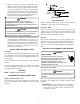
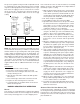
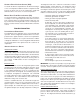
See below for typical propane gas piping.
200 PSIG
Maximum
5 to 15 PSIG
(20 PSIG Max.)
Continuous
11" W.C.
Second Stage
Regulator
First Stage
Regulator
TYPICAL PROPANE GAS PIPING
ROOF TOP LOCATION AND INSTALLATION
The gas supply piping location and installation for roof top
units must be in accordance with local codes or, in the ab-
sence of locals codes, with ordinances of the latest edition of
the National Fuel Gas Code (ANSI Z223.1).
A manual gas shutoff valve must be field installed external to
the roof top unit. In addition, a drip leg must be installed near
the inlet connection. A ground joint union connection is re-
quired between the external shutoff valve and the unit con-
nection to the gas valve to permit removal of the burner as-
sembly for servicing.
1. Route gas piping to unit so that it does not interfere
with the removal of access panels. Support and align
piping to prevent strains or misalignment of the
manifold assembly.
2. All units are furnished with standard female NPT pipe
connections. Connection pipe sizes for CPG090
through 300 units is 3/4" NPT The size of the gas
supply piping to the unit must be based on length of
run, number of units on the system, gas
characteristics, BTU requirement and available supply
pressure. All piping must be done in accordance with
local codes or, in the absence of local codes, with the
latest edition of the National Fuel Gas Code (ANSI
Z223.1).
NOTE: The gas connection size at the unit does NOT
establish the size of the supply line.
3. These units are designed for either natural or propane
(LP) gas and are specifically constructed at the factory
for only one of these fuels. The fuels are NOT
interchangeable. However, the furnace can be
converted in the field from natural gas to LP gas with
the appropriate factory kit (see unit Technical Manual
for the appropriate kit). Only a qualified contractor,
experienced with natural and propane gas systems,
should attempt conversion. Kit instructions must be
followed closely to assure safe and reliable unit
operation.
4. With all units on a common line operating under full
fire, natural gas main supply pressure should be
adjusted to approximately 7.0" w.c., measured at the
unit gas valve. If the gas pressure at the unit is greater
than 10.5" w.c., the contractor must furnish and install
an external type positive shutoff service pressure
regulator. The unit will not function satisfactorily if
supply gas pressure is less than 5.5" w.c. or greater
than 10.5" w.c..
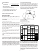
NOTE: A minimum horizontal distance of 48"
between the regulator and the furnace flue discharge
is required.
5. With all units on a common line operating under full
LP gas main supply pressure should be at least 11.0"
w.c. and must be no greater than 14.0" w.c., measured
at the unit gas valve. Unit will not function satisfactorily
if supply gas pressure is less than 11.0" w.c. or greater
than 14.0" w.c..