TECHNICAL MANU AL MANUAL GDS8 & GHS8 33-3/8" 80% Gas Furnace Units • Refer to Service Manual RS6610004 for installation, operation, and troubleshooting information. • All safety information must be followed as provided in the Service Manual. • Refer to the appropriate Parts Catalog for part number information. • Model numbers listed on page 3. This manual is to be used by qualified, professionally trained HVAC technicians only.
PRODUCT IDENTIFICATION The model and manufacturing number are used for positive identification of component parts used in manufacturing. Please use these numbers when requesting service or parts information.
PRODUCT IDENTIFICATION The model and manufacturing number are used for positive identification of component parts used in manufacturing. Please use these numbers when requesting service or parts information.
PRODUCT DESIGN General Operation The G*S8 furnaces are equipped with an electronic ignition device used to light the burners and an induced draft blower to exhaust combustion products. An interlock switch prevents furnace operation if the inner blower door is not in place. Keep the blower access door in place except for inspection and maintenance. (See illustration on pages 5 and 6.) This furnace is also equipped with a self-diagnosing electronic control module.
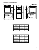
PRODUCT DIMENSIONS MODEL A B GHS80453AXC* 14 1/2" 12 1/2" GHS80704BXC* 17 1/2" 16" GHS80905CXC* 21" 19 1/2" MODEL A B 14 1/2" 12 1/2" GDS80904BXC* 17 1/2" 16" GDS81155CXC* 21" 19 1/2" GDS80453AXC* GDS80703AXC* 5
PRODUCT DESIGN GHS8 Pressure Switch Trip Points And Usage Chart Model Trip Point ID Blower Pressure Switch ID Blower Pressure Switch Part # GHS80453AXC* -0.80 0130F00042 GHS80704BXC* -0.70 B1370158 GHS80905CXC* -0.70 B1370158 For installations in Canada, the GHS furances are certified only to 4,500 ft. * Negative pressure readings are in inches of water column (*w.c.
PRODUCT DESIGN GDS8 Presssure Switches Model Part No. Opens* GDS80453AXC* B1370142 -0.60 GDS80703AXC* B137158 -0.70 GDS80904BXC* B1370142 -0.60 GDS81155CXC* B137158 -0.
PRODUCT DESIGN Coil Matches: A large array of Amana® brand coils are available for use with the GHS8 furnaces, in horizontal applications and for the GDS8 for downflow applications. These coils are available in both cased and uncased models (with the option of a field installed TXV expansion device). These 80% furnaces match up with the existing Amana® brand coils as shown below.
PRODUCT DESIGN Thermostats: NOTE: Complete lineup of thermostats can be found in the Thermostat Specification Sheets. Filters: Filters are required with this furnace and must be provided by the installer. The filters used must comply with UL900 or CAN/ULCS111 standards. Installing this furnace without filters will void the unit warranty Upflow Filters This furnace has provisions for the installation of return air filters at the side and/or bottom return.
PRODUCT DESIGN Counterflow Filters This furnace has provisions for the installation of return air filters at the counterflow top return. The furnace will accommodate the following filter sizes depending on cabinet size: Counterflow Top Return Return Air Optional Access Door Cabinet Width "A" Min 21 24 1/2 21 24 1/2 21 24 1/2 Filter Area Qty Filter Size Dimension "A" (in) (in) (in2) 600 2 15 X 20 X 1 800 2 20 X 20 X 1 1000 2 25 X 20 X 1 13.0 11.3 18.8 17.7 24.3 23.
FURNACE SPECIFICATIONS MODEL GDS8 GDS80453AXC* GDS80703AXC* GDS80904BXC* GDS81155CXC* (1) 45,000 70,000 90,000 115,000 36,000 56,000 72,000 92,000 80% 80% 80% 80% .20 - .50 .20 - .50 .20 - .50 .20 - .50 Temperature Rise (°F) 35-65 30-60 35-65 40 - 70 Pressure Switch Trip Point (" w.c.) -0.60 -0.70 -0.60 -0.70 10 X 6 10 x 6 10 x 8 10 x 10 1/3 1/3 1/2 3/4 Btuh Input (US) High Fire Output (US) High Fire (1) (2) A.F.U.E. Rated External Static (" w.c.
FURNACE SPECIFICATIONS MODEL GHS8 GHS80453AXC* GHS80704BXC* GHS80905CXC* 45,000 70,000 90,000 36,000 56,000 72,000 Output, LP (BTUH) 32,000 48,000 64,000 (2) 80.0% 80.0% 80.0% 0.20 - 0.50 0.20 - 0.50 0.20 - 0.50 15 - 45 30 - 60 35 - 65 -0.80 -0.70 -0.70 11” x 6” 11” x 8” 11” x 10” 1/2 3/4 3/4 Input, Natural Gas (BTUH) (1) (1) Output, Natural Gas (BTUH) A.F.U.E. Rated External Static (" w.c.) Temperature Rise (°F) Pressure Switch Trip Point (" w.c.
BLOWER PERFORMANCE SPECIFICATIONS GHS8 BLOWER PERFORMANCE (CFM & Temperature Rise vs. External Static Pressure) Tons AC Model ( Heating Speed As Shipped GHS8 0453AXC (Med)² GHS8 0704BXC (Med)² GHS8 0905CXC (Med)² ) Motor Speed at 0.5" ESP EXTERNAL STATIC PRESSURE (Inches Water Column) 0.1 0.2 0.3 0.4 0.5 0.6 0.7 0.8 CFM RISE CFM RISE CFM RISE CFM RISE CFM RISE CFM CFM CFM High 3.0 1,739 19 1,656 20 1,601 21 1,551 21 1,513 22 1,460 1,413 1,353 Med 2.
BLOWER PERFORMANCE SPECIFICATIONS GDS8 BLOWER PERFORMANCE (CFM & Temperature Rise vs. External Static Pressure) ( ) Heating Speed As Shipped GDS8 0453AXC (Med)² GDS8 0703AXC (Med)² GDS8 0904BXC (Med)² GDS8 1155CXC (Med)² EXTERNAL STATIC PRESSURE (Inches Water Column) Tons AC Model Motor Speed at 0.5" ESP 0.1 0.2 0.3 0.4 0.5 0.6 0.7 0.8 CFM RISE CFM RISE CFM RISE CFM RISE CFM RISE CFM CFM CFM HIGH 3.0 1,353 25 1,290 26 1,246 27 1,199 28 1,149 29 1,116 1,116 1,099 MED 2.
TEMPERATURE RISE 10 20 30 40 50 60 70 30 80 90 100 40 50 60 700 600 CFM 90 100 2000 2200 2400 CFM 1800 1600 1400 OUTPUT BTU/HR x 1000 80 1200 1100 1000 900 70 800 FORMULAS 110 120 130 140 BTU OUTPUT = CFM x 1.08 x RISE BTU OUTPUT RISE = ÷ CFM 1.
WIRING DIAGRAMS G*S8 HIGH VOLTAGE! DISCONNECT ALL POWER BEFORE SERVICING OR INSTALLING THIS UNIT. MULTIPLE POWER SOURCES MAY BE PRESENT. FAILURE TO DO SO MAY CAUSE PROPERTY DAMAGE, PERSONAL INJURY OR DEATH. BOX Wiring is subject to change, always refer to the wiring diagram on the unit for the most up-to-date wiring.