® TECHNICAL MANU AL MANUAL GKS9 40" 90% Gas Furnaces • Refer to Service Manual RS6610004* for installation, operation, and troubleshooting information. • All safety information must be followed as provided in the Service Manual. • Refer to the appropriate Parts Catalog for part number information. • Model numbers listed on page 3. ® C This manual is to be used by qualified, professionally trained HVAC technicians only.
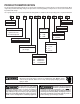
PRODUCT IDENTIFICATION The model and manufacturing number are used for positive identification of component parts used in manufacturing. When engineering and manufacturing changes take place where interchangeability of components are affected, the manufacturing number will change. It is very important to use the model and manufacturing numbers at all times when requesting service or parts information.
PRODUCT IDENTIFICATION The model and manufacturing number are used for positive identification of component parts used in manufacturing. When engineering and manufacturing changes take place where interchangeability of components are affected, the manufacturing number will change.
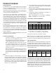
PRODUCT DESIGN General Operation The GKS9 furnaces are equipped with an electronic ignition device used to light the burners and an induced draft blower to exhaust combustion products. An interlock switch prevents furnace operation if the blower door is not in place. Keep the blower access door in place except for inspection and maintenance. This furnace is also equipped with a self-diagnosing electronic control module.
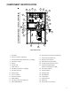
COMPONENT IDENTIFICATION BURNER COMPARTMENT 3 6 6 5 4 7 8 9 10 25 11 12 13 2 14 1 15 27 17 29 18 26 BLOWER COMPARTMENT 16 17 28 18 19 24 20 21 23 22 Upflow/Horizontal 1 Gas Valve 16 Electrical Connection Inlets (Alternate) 2 Gas Line Entrance (Alternate) 17 Coil Front Cover Drain Port 3 Combustion Air Intake Connection / “Coupling” 18 Drain Line Penetrations 4 Hot Surface Igniter 19 Blower Door Interlock Switch 5 Burners 20 24-Volt Thermostat Connections 6 Rollou
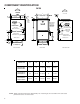
COMPONENT IDENTIFICATION GKS9 AIR DISCHARGE AIR DISCHARGE A B (DISCHARGE) 20 13/16 C AIR INTAKE PIPE 2" PVC STANDARD GAS SUPPLY HOLE CONDENSATE DRAIN TRAP w/ 3/4" PVC DISCHARGE (RIGHT OR LEFT SIDE) HIGH VOLTAGE ELECTRICAL HOLE HIGH VOLTAGE ELECTRICAL HOLE LEFT SIDE DRAIN LINE HOLES 1 1/2 DRAIN TRAP LOW VOLTAGE ELECTRICAL HOLE 2 LOW VOLTAGE ELECTRICAL HOLE SIDE CUT-OUT 1 5/8 1 RIGHT SIDE DRAIN LINE HOLES SIDE CUT-OUT 22 1/16 UNFOLDED FLANGES UNFOLDED FLANGES 23 9/16 FOLDED FLANGES FOLDED FL
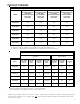
PRODUCT DESIGN PRESSURE SWITCH TRIP POINTS AND USAGE CHART MODEL NEGATIVE PRESSURE ID BLOWER WITH FLUE NOT FIRING TYPICAL SEA LEVEL DATA NEGATIVE PRESSURE ID BLOWER WITH FLUE FIRING TYPICAL SEA LEVEL DATA NEGATIVE PRESSURE COIL COVER WITH FLUE NOT FIRING TYPICAL SEA LEVEL DATA NEGATIVE PRESSURE COIL COVER WITH FLUE FIRING TYPICAL SEA LEVEL DATA GKS90453BX* -1.40 -1.20 -0.52 -0.37 GKS90703BX* -1.30 -1.10 -0.52 -0.37 GKS90704CX* -1.30 -1.10 -0.52 -0.37 GKS90904CX* -1.10 -0.95 -0.
PRODUCT DESIGN T.O.D.
PRODUCT DESIGN Coil Matches: A large array of Amana® brand coils are available for use with the GKS9 furnaces, in either upflow, counterflow, or horizontal applications. These coils are available in both cased and uncased models (with the option of a field installed TXV expansion device). These 90%+ furnaces match up with the existing Amana® brand coils as shown in the chart below.
PRODUCT DESIGN Thermostats: NOTE: Complete lineup of thermostats can be found in the Thermostat Specification Sheets. Filters: Filters are required with this furnace and must be provided by the installer. The filters used must comply with UL900 or CAN/ULCS111 standards. Installing this furnace without filters will void the unit warranty. Upflow Filters This furnace has provisions for the installation of return air filters at the side and/or bottom return.
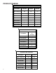
FURNACE SPECIFICATIONS GKS9 0453BX* GKS9 0703BX* GKS9 0704CX* GKS9 0904CX* GKS9 0905DX* GKS9 1155DX* Input (US) 46,000 69,000 69,000 92,000 92,000 115,000 Output (US) 42,800 64,400 63,900 86,000 86,000 106,500 Input (CAN) 46,000 69,000 69,000 92,000 92,000 115,000 Output (CAN) 42,800 64,400 63,900 86,000 85,300 106,500 92.1% 92.1% 92.1% 92.1% 92.1% 92.1% Rated External Static (" w.c.) .20 - .50 .20 - .50 .20 - .50 .20 - .50 .20 - .50 .20 - .
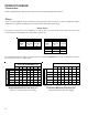
BLOWER PERFORMANCE SPECIFICATIONS BLOWER PERFORMANCE (CFM & Temperature Rise vs. External Static Pressure) ( EXTERNAL STATIC PRESSURE (Inches Water Column) Tons AC Model ) Heating Speed As Shipped Motor Speed at 0.5" ESP 0.1 0.2 0.3 0.4 0.5 0.6 0.7 0.8 CFM RISE CFM RISE CFM RISE CFM RISE CFM RISE CFM CFM CFM HIGH 3.0 1352 --- 1318 --- 1260 --- 1202 --- 1128 --- 1044 955 853 GKS90453BX* MED 2.
TEMPERATURE RISE 10 20 30 40 50 60 70 30 80 90 100 40 50 60 700 600 CFM 90 100 2000 2200 2400 CFM 1800 1600 1400 OUTPUT BTU/HR x 1000 80 1200 1100 1000 900 70 800 FORMULAS 110 120 130 140 BTU OUTPUT = CFM x 1.08 x RISE BTU OUTPUT RISE = ÷ CFM 1.
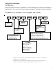
WIRING DIAGRAMS GKS9*****X** BLOWER COMPARTMENT DOOR SWITCH (OPEN WHEN DOOR OPEN) OR 24 VAC HUMIDIFIER GY 24 VAC INTEGRATED CONTROL MODULE HUMIDIFIER TR (6) GND GND (8) C2 MVC (9) 115 VAC 24V THERMOSTAT CONNECTIONS C R G GAS VALVE N O BK BL INTEGRATED CONTROL MODULE GY 3 2 1 6 5 4 PK OR 9 8 7 BL 12 11 10 YL GR OR GY 24V THERMOSTAT CONNECTIONS OR FUSE ID BLOWER PRESSURE SWITCH OPTIONAL FRONT COVER PRESSURE SWITCH BK WH BK C MV(12) C W Y M1 G PS (10) NO C