TECHNICAL MANU AL MANUAL GMH95 40" 95% Gas Furnace • Refer to Service Manual RS6610004 for installation, operation, and troubleshooting information. • All safety information must be followed as provided in the Service Manual. • Refer to the appropriate Parts Catalog for part number information. • Model numbers listed on page 3. ® C This manual is to be used by qualified, professionally trained HVAC technicians only.
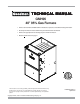
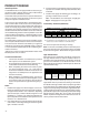
PRODUCT IDENTIFICATION The model and manufacturing number are used for positive identification of component parts used in manufacturing. Please use these numbers when requesting service or parts information.
PRODUCT IDENTIFICATION The model and manufacturing number are used for positive identification of component parts used in manufacturing. Please use these numbers when requesting service or parts information. GMH950453BXA* GMH950703BXA* GMH950704CXA* GMH950904CXA* GMH950905DXA* GMH951155DXA* WARNING The United States Environmental Protection Agency (“EPA”) has issued various regulations regarding the introduction and disposal of refrigerants introduced into this unit.
PRODUCT DESIGN General Operation The GMH95 furnaces are equipped with an electronic ignition device used to light the burners and an induced draft blower to exhaust combustion products. An interlock switch prevents furnace operation if the blower door is not in place. Keep the blower access door in place except for inspection and maintenance. This furnace is also equipped with a self-diagnosing electronic control module.
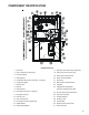
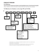
COMPONENT IDENTIFICATION Upflow/Horizontal 1 Gas Valve 17 Electrical Connection Inlets (Alternate) 2 Gas Line Entrance (Alternate) 18 Coil Front Cover Pressure Tap 3 Pressure Switch 19 Coil Front Cover Drain Port 4 Gas Manifold 20 Drain Line Penetrations 5 Combustion Air Intake Connection / “Coupling” 21 Drain Trap 6 Hot Surface Igniter 22 Blower Door Interlock Switch 7 Rollout Limit 23 Capacitor 8 Burners 24 Integrated Control Module 9 Flame Sensor (with fuse and diagnostic LED)
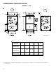
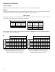
COMPONENT IDENTIFICATION GMH95*****XA* AIR DISCHARGE AIR DISCHARGE AIR INTAKE PIPE 2" PVC RIGHT SIDE DRAIN LINE HOLES 1 1/2 2 1 5/8 1 UNFOLDED FLANGES UNFOLDED FLANGES FOLDED FLANGES FOLDED FLANGES RIGHT SIDE VIEW Cabinet Size A B C D E GMH950453BXA* GMH950703BXA* 17-1/2 16 12-15/16 12-1/8 13-5/8 GMH950704CXA* GMH950904CXA* 21 19-1/2 15-15/16 16 17-1/2 GMH950905DXA* GMH951155DXA* 24-1/2 23 20-7/16 19-3/8 20-7/8 All dimensions are in inches.
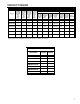
PRODUCT DESIGN PRESSURE SWITCH TRIP POINTS AND USAGE CHART MODEL NEGATIVE PRESSURE ID BLOWER WITH FLUE NOT FIRING TYPICAL SEA LEVEL (1) DATA NEGATIVE PRESSURE ID BLOWER WITH FLUE FIRING TYPICAL SEA LEVE (2) DATA NEGATIVE PRESSURE COIL COVER WITH FLUE NOT FIRING TYPICAL SEA LEVEL (1) DATA PRESSURE SWITCH TRIP POINTS AND USAGE NEGATIVE PRESSURE 0 to 7,000 ft. 7,001 to 11,000 ft.
PRODUCT DESIGN ROLLOUT LIMIT SW ITCHES Part Number 10123514 or 10123533 Open Setting (°F) 200 GMH950453BXA* 1 GMH950703BXA* 2 GMH950704CXA* 2 GMH950904CXA* 2 GMH950905DXA* 2 GMH951155DXA* 2 AUXILIARY LIMIT SWITCHES Part Number 10123535 10123519 Open Setting (°F) 150 160 GMH950453BXA* 1 GMH950703BXA* 1 GMH950704CXA* 1 GMH950904CXA* 1 GMH950905DXA* 1 GMH951155DXA* 8 1
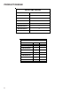
PRODUCT DESIGN Coil Matches: A large array of Amana® brand coils are available for use with the GMH95 furnaces, in either upflow or horizontal applications. These coils are available in both cased and uncased models (with the option of a field installed TXV expansion device). These 95%+ furnaces match up with the existing Amana® brand coils as shown in the chart below.
PRODUCT DESIGN Thermostats: NOTE: Complete lineup of thermostats can be found in the Thermostat Specification Sheets. Filters: Filters are required with this furnace and must be provided by the installer. The filters used must comply with UL900 or CAN/ULCS111 standards. Installing this furnace without filters will void the unit warranty. Upflow Filters This furnace has provisions for the installation of return air filters at the side and/or bottom return.
FURNACE SPECIFICATIONS GMH95 GMH95 0453BXA* GMH95 0703BXA* GMH95 0704CXA* GMH95 0904CXA* GMH95 0905DXA* GMH95 1155DXA* Input (US) 46,000 69,000 69,000 92,000 92,000 115,000 Output (US) 44,400 66,400 66,900 89,000 88,400 110,500 Input (CAN) 46,000 69,000 69,000 92,000 92,000 115,000 Output (CAN) 44,400 66,400 66,900 89,000 89,400 110,500 95.0% 95.0% 95.0% 95.0% 95.0% 95.0% Rated External Static (" w.c.) .20 - .50 .20 - .50 .20 - .50 .20 - .50 .20 - .50 .20 - .
BLOWER PERFORMANCE SPECIFICATIONS BLOWER PERFORMANCE (CFM & Temperature Rise vs. External Static Pressure) ( EXTERNAL STATIC PRESSURE (Inches Water Column) Tons AC Model ) Heating Speed As Shipped Motor Speed at 0.5" ESP 0.1 0.2 0.3 0.4 0.5 0.6 0.7 0.8 CFM RISE CFM RISE CFM RISE CFM RISE CFM RISE CFM CFM CFM HIGH 3.0 1352 29 1318 30 1260 31 1202 33 1128 35 1044 955 853 GMH950453BXA* MED 2.
TEMPERATURE RISE 10 20 30 40 50 60 70 30 80 90 100 40 50 60 700 600 CFM 90 100 2000 2200 2400 CFM 1800 1600 1400 OUTPUT BTU/HR x 1000 80 1200 1100 1000 900 70 800 FORMULAS 110 120 130 140 BTU OUTPUT = CFM x 1.08 x RISE BTU OUTPUT RISE = ÷ CFM 1.
WIRING DIAGRAMS GMH95[0453,0704,0905]*XAB GMH95[0703,0904,1155]*XAC BLOWER COMPARTMENT DOOR SWITCH (OPEN WHEN DOOR OPEN) OR 24 VAC HUMIDIFIER GY 24 VAC INTEGRATED CONTROL MODULE HUMIDIFIER TR (6) GND GND (8) C MVC (9) 115 VAC 24V THERMOSTAT CONNECTIONS C BK GY 3 2 1 6 5 4 9 8 7 BL 12 11 10 YL INTEGRATED CONTROL MODULE OFF 2ND STAGE DELAY MODE HEAT OFF DELAY * * 2 HLO (1) R RO2 (11) RO1 (5) 24 VAC XFMR-H 115 VAC FLAME SENSOR WH FS HOT SURFACE IGNITER IGN BR YL HE LO AT
WIRING DIAGRAMS GMH95[0453,0704,0905]*XAC GMH95[0703,0904,1155]*XAD BLOWER COMPARTMENT DOOR SWITCH (OPEN WHEN DOOR OPEN) OR 24 VAC HUMIDIFIER GY 24 VAC C GAS HI VALVE PM G R W BK G OR 3 2 1 5 4 9 8 7 12 11 10 2ND STAGE DELAY MODE HEAT OFF DELAY * * PK GY BL YL HLI (7) W GR RO2 (11) RO1 (5) MANUAL RESET ROLLOUT LIMIT CONTROL(S) (SINGLE CONTROL ON 45K BTU) 24 VAC BR TH (3) 40 VA TRANSFORMER TERMINALS FS WH XFMR-H 115 VAC XFMR-H FLAME SENSOR PK 2 WH FS HOT SURFACE I