TECHNICAL MANU AL MANUAL TM ACVC9/AMVC95 GCVC9/GMVC95 90%-95% Gas Furnace Units • Refer to Service Manual RS6200004 for installation, operation, and troubleshooting information. • All safety information must be followed as provided in the Service Manual. • Refer to the appropriate Parts Catalog for part number information. • Models listed on page 3. ® C US This manual is to be used by qualified, professionally trained HVAC technicians only.
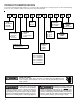
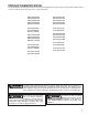
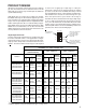
PRODUCT IDENTIFICATION The model and manufacturing number are used for positive identification of component parts used in manufacturing. Please use these numbers when requesting service or parts information.
PRODUCT IDENTIFICATION The model and manufacturing number are used for positive identification of component parts used in manufacturing. Please use these numbers when requesting service or parts information.
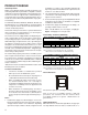
PRODUCT DESIGN The GCVC9, GCVC95, GMVC95, AMVC95, ACVC9 and ACVC95 furnaces are equipped with an electronic ignition device to light the burners and an induced draft blower to exhaust combustion products. An interlock switch prevents furnace operation if the blower door is not in place. Keep the blower access doors in place except for inspection and maintenance. These furnaces are also equipped with a self-diagnosing electronic control module.
PRODUCT DESIGN quired due to the natural reduction in the density of both the gas fuel and combustion air as altitude increases. The kit will provide the proper design certified input rate within the specified altitude range. High altitude kits are purchased according to the installation altitude and usage of either natural or propane gas. Refer to the chart above for a tabular listing of appropriate altitude ranges and corresponding manufacturer’s high altitude Natural Gas and Propane Gas kits.
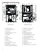
COMPONENT IDENTIFICATION 9 7 5 10 10 32 4 11 3 12 3 * 2 11 25 24 * * 28 13 15 * * 1 * * 14 16 17 18 31 18 19 19 20 3 3 17 15 31 21 16 30 18 18 19 28 14 29 20 20 19 20 13 12 2 21 23 26 27 25 Upflow/Horizontal 9 7 8 7 6 4 1 Counterflow /Horizontal 1 Two-Stage Gas Valve 18 Coil Front Cover Pressure Tap 2 Gas Line Entrance (Alternate) 19 Coil Front Cover Drain Port 3 Pressure Switch(es) 20 Drain Line Penetrations 4 Gas Manifold 21 Drain Trap 5 Combusti
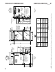
LEFT SIDE VIEW 23 9/16 BOTTOM KNOCK-OUT 1 3/4 2 5/8 11 3/4 17 1/2 21 24 1/2 UNITS 0453BX* 0704CX* 0905CX* 0905DX* 1155DX* SMALL MEDIUM LARGE A BOTTOM KNOCK-OUT C CABINET SIZE 30 1/4 19 3/16 DRAIN TRAP AIR INTAKE PIPE 2" PVC B (DISCHARGE AIR) A 20 3/8 16 3/8 12 3/8 C 32 13/16 18 5/8 14 5/8 12 5/8 D 19 3/16 4 1/8 All dimensions are in inches.
A 21 24 1/2 UNITS 0704CX* 0714CX* 0905DX* 0915DX* 1155DX* CABINET SIZE MEDIUM LARGE 9 13/16 11 1/2 15 1/2 28 5/16 23 19 B 18 5/8 14 5/8 D All dimensions are in inches.
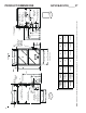
PRODUCT DESIGN PRESSURE SWITCH TRIP POINTS AND USAGE CHART MODEL NEGATIVE PRESSURE ID BLOWER WITH FLUE NOT FIRING TYPICAL SEA LEVEL NEGATIVE PRESSURE ID BLOWER WITH FLUE FIRING TYPICAL SEA LEVEL NEGATIVE PRESSURE COIL COVER WITH FLUE NOT FIRING TYPICAL SEA LEVEL NEGATIVE PRESSURE COIL COVER WITH FLUE FIRING TYPICAL SEA LEVEL DATA(1) DATA(2) DATA(1) DATA(2) LOW FIRE HIGH FIRE LOW FIRE HIGH FIRE LOW FIRE HIGH FIRE LOW FIRE HIGH FIRE GMVC950453BX* GMVC950704CX* AMVC950453BX* AMVC950704CX* -0
-0.10 -0.10 -0.37 -0.10 -0.37 -0.10 -0.37 GMVC 950905CX* AMVC950905CX* GMVC 950905DX* GMVC 951155DX* AMVC950905DX* AMVC951155DX* GCVC90704C X* ACVC90704CX* GCVC950714CX* ACVC950714CX* GCVC90905D X* ACVC90905DX* GCVC950915DX* ACVC950915DX* GCVC91155D X* -0.37 -0.10 -0.37 -0.10 -0.37 -0.10 -0.10 -0.10 20197313 0130F00070 20197313 0130F00070 20197313 20197308 0130F00070 20197308 COIL COVER PRESSU RE SWITCH PART # -0.20 -0.80 -0.20 -0.80 -0.20 -0.50 -0.60 -0.30 -0.
PRODUCT DESIGN PRIMARY LIMIT Part Number 20162903 20162904 20162905 20162907 20162908 0130F00105 Open Setting (°F) 160 150 145 155 170 130 GMVC950453BX* AMVC950453BX* --- --- 1 --- --- --- GMVC950704CX* AMVC950704CX* --- --- --- 1 --- --- GMVC950905CX* AMVC950905CX* --- --- --- --- --- 1 GMVC950905DX* AMVC950905DX* --- --- 1 --- --- --- GMVC951155DX* AMVC951155DX* --- 1 --- --- --- --- GCVC90704CX* ACVC90704CX* 1 --- --- --- --- --- GCVC950714CX* ACVC
PRODUCT DESIGN AUXILIARY LIMIT SWITCHES 12 Part Number 10123534 10123535 10123537 10123536 10123533 0130F00038 Open Setting (°F) 220 150 190 180 200 120 GMVC950453BX* AMVC950453BX* --- 2 --- --- --- --- GMVC950704CX* AMVC950704CX* --- --- 2 --- --- --- GMVC950905CX* AMVC950905CX* --- --- --- --- --- 2 GMVC950905DX* AMVC950905DX* --- --- --- 2 --- --- GMVC951155DX* AMVC951155DX* --- --- --- --- 2 --- GCVC90704CX* ACVC90704CX* 2 --- --- --- --- --- GCV
PRODUCT DESIGN Coil Matches: A large array of Amana® brand coils are available for use with the GCVC9 and ACVC9 furnaces, in either counterflow or horizontal applications & with GMVC95 and AMVC95 furnaces, in either upflow or horizontal applications. These coils are available in both cased and uncased models (with the option of a field installed TXV expansion device). These 92%+ and 95%+ furnaces match up with the existing Amana® brand coils as shown in the chart below.
PRODUCT DESIGN Thermostats: ComfortNet™ CTK01A* Thermostat Kit Filters: Filters are required with this furnace and must be provided by the installer. The filters used must comply with UL900 or CAN/ULCS111 standards. Installing this furnace without filters will void the unit warranty Upflow Filters Return air filters may be installated at the furnace side and/or bottom return openings.
PRODUCT DESIGN Input__Airflow U PFLOW COOLING A IRFLOW REQU IREMEN T (CFM) 600 800 1000 1200 1400 1600 1800 2000 04 53__X* 207* 207* 24 0 288 --- --- --- --- 07 04__X* --- --- 318* 318* 336 384 --- --- 09 05__X* --- --- --- 413* 413* 413* 432 480 11 55__X* --- --- --- 437* 437* 437* 432 480 Input Airflow COUNTER FLOW COOLING A IRFLOW REQU IREMEN T (CFM) 600 800 1000 1200 1400 1600 1800 2000 0704 __X* 0714 __X* --- --- 316* 316* 336 384 --- ---
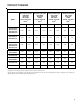
FURNACE SPECIFICATIONS MODEL GMVC95 GMVC950453BX* GMVC950704CX* GMVC950905CX* GMVC950905DX* GMVC951155DX* Btuh Input (US) High Fire 46,000 69,000 92,000 92,000 115,000 Output (US) High Fire 44,300 66,900 88,800 88,800 111,100 Btuh Input (US) Low Fire 32,000 48,000 64,000 64,000 80,000 Output (US) Low Fire 30,800 46,400 61,700 61,700 77,400 95% 95% 95% 95% 95% .10 - .50 .10 - .50 .10 - .50 .10 - .50 .10 - .
FURNACE SPECIFICATIONS MODEL AMVC95 AMVC950453BX* AMVC950704CX* AMVC950905CX* AMVC950905DX* AMVC951155DX* Btuh Input (US) High Fire 46,000 69,000 92,000 92,000 115,000 Output (US) High Fire 44,300 66,900 88,800 88,800 111,100 Btuh Input (US) Low Fire 32,000 48,000 64,000 64,000 80,000 Output (US) Low Fire 30,800 46,400 61,700 61,700 77,400 99% 95.5% 95.7% 95.7% 95.8% .10 - .50 .10 - .50 .10 - .50 .10 - .50 .10 - .
FURNACE SPECIFICATIONS MODEL Btuh Input (US) High Fire GCVC9 GCVC90704CX* GCVC90905DX* GCVC91155DX* 69,000 92,000 115,000 Output (US) High Fire 65,300 86,500 109,000 Btuh Input (US) Low Fire 48,000 64,000 80,000 Output (US) Low Fire 45,000 60,100 77,400 A.F.U.E. 93.0% 92.0% 93% .10 - .50 .10 - .50 .10 - .50 30 - 60 30 - 60 40 - 70 High Stage Pressure Switch Trip Point (" w.c.) -0.55 -0.55 -0.55 Low Stage Pressure Switch Trip Point (" w.c.) -0.20 -0.20 -0.
FURNACE SPECIFICATIONS MO DEL GCVC95 G C V C 95 0 71 4 CX * G C V C9 5 09 1 5D X * B tu h In p ut (US ) Hig h Fire 69 ,0 0 0 9 2 ,0 00 O u tp ut (US ) Hig h Fire 65 ,3 0 0 8 6 ,5 00 B tu h In p ut (US ) Lo w Fire 48 ,0 0 0 6 4 ,0 00 O u tp ut (US ) Lo w Fire 45 ,0 0 0 6 0 ,1 00 A .F. U.E . 9 5. 0% 95 .0 % R at ed E x te rn al S t at ic (" w .c .) .1 0 - . 50 .1 0 - .5 0 Te m p era tu re R is e (° F ) 25 - 55 25 - 55 H ig h S ta ge P re s s u re S witc h Trip P o in t (" w .c .) -1 .
FURNACE SPECIFICATIONS MOD EL ACVC9 A C V C 90704C X * A C V C 90905D X * B tu h In p u t (U S ) H ig h F ire 6 9 ,0 0 0 92,000 O u t p u t (U S ) H ig h F ire 6 5 ,3 00 86,500 B tu h In p u t (U S ) L o w F ire 4 8 ,0 0 0 64,000 O u t p u t (U S ) L o w F ire 45,000 60,100 A . F .U .E . 93.3% 92.7% .1 0 - .5 0 .1 0 - .5 0 30 - 60 30 - 60 H ig h S ta g e P re s s u re S w it c h Trip P o in t (" w .c . ) -0 . 5 5 -0 . 5 5 L o w S ta g e P re s s u re S w itc h Trip P o in t (" w .
FURNACE SPECIFICATIONS MO DEL ACVC95 A C V C9 5 07 1 4C X * A C V C9 50 9 15 D X * B tu h In p ut (U S ) H ig h F ire 69 ,0 0 0 92 ,0 0 0 O u tp ut (U S ) Hig h F ire 65 ,3 0 0 86 ,5 0 0 B tu h In p ut (U S ) Lo w F ire 48 ,0 0 0 64 ,0 0 0 O u tp ut (U S ) Lo w F ire 45 ,0 0 0 60 ,1 0 0 A .F . U.E . 9 5. 0% 9 5. 0% R at ed E x te rn al S t at ic (" w .c .) .1 0 - . 50 .1 0 - .
BLOWER PERFORMANCE SPECIFICATIONS GMVC95/AMVC95 Heating Speed Charts GMVC950453BX* AMVC950453BX* (Ris e Range: 30 - 60°F) Heating Speed Tap A B C D GMVC950704CX* AMVC950704CX* (Ris e Range: 30 - 60°F) Minus (-) Norm al Low Stage CFM at .1" - .5" w.c. ESP 495 550 High Stage CFM at .1" - .5" w.c.
BLOWER PERFORMANCE SPECIFICATIONS GMVC95/AMVC95 Heating Speed Charts GMVC950905DX* AMVC950905DX* (Rise Range: 30 - 60°F) Heating Speed Tap A B C D GMVC951155DX* AMVC951155DX* (Rise Range: 35 - 65°F) Adjust Tap Low Stage CFM at .1" - .5" w.c. ESP High Stage CFM at .1" - .5" w.c.
BLOWER PERFORMANCE SPECIFICATIONS GMVC95/AMVC95 High (Single) Stage Cooling Speed Charts GMVC950453BX* AMVC950453BX* Cooling Speed Tap A B C D Adjus t Tap CFM at Cooling .1" - .8" Speed w.c.
BLOWER PERFORMANCE SPECIFICATIONS GMVC95/AMVC95 Low Stage Cooling Speed Charts GMVC950453BX* AMVC950453BX* Cooling Speed Tap A B C D Adjus t Tap CFM at Cooling .1" - .8" Speed w.c.
BLOWER PERFORMANCE SPECIFICATIONS GMVC95/AMVC95 Continuous Fan Speed Chart Furnace Maxim um CFM Continuous Fan Speed 1,2 1400 420 1760 530 2200 660 GMVC950905DX* AMVC950905DX* 2200 660 GMVC951155DX* AMVC951155DX* 2200 660 Model GMVC950453BX* AMVC950453BX* GMVC950704CX* AMVC950704CX* GMVC950905CX* AMVC950905CX* 1 Continuous fan s peed is 30% of furnace m axim um CFM Three continuous fan s peeds are pos s ible with the CTK01AA therm os tat: 30% , 50% , and 70% of furnace m axim um CFM 2 GCVC9
BLOWER PERFORMANCE SPECIFICATIONS GCVC9/ACVC9 Heating Speed Charts GCVC90704CX* ACVC90704CX* (Rise Range: 30 - 60°F) Heating Speed Tap A B C D Adjust Tap GCVC90905DX* ACVC90905DX* (Rise Range: 30 - 60°F) High Stage Low Stage CFM Rise CFM at .1" - .5" w.c. at .1" - .5" w.c.
BLOWER PERFORMANCE SPECIFICATIONS GCVC95/ACVC95 Heating Speed Charts GCVC950714CX* ACVC950714CX* (Rise Range: 25 - 55°F) Heating Adjust Speed Tap Tap A B C D Minus(-) Normal Plus (+) Minus(-) Normal Plus (+) Minus(-) Normal Plus (+) Minus(-) Normal Plus (+) GCVC950915DX* ACVC950915DX* (Rise Range: 25 - 55°F) High Stage Low Stage CFM Rise CFM at .1" - .5" w.c. at .1" - .5" w.c.
BLOWER PERFORMANCE SPECIFICATIONS GCVC9/ACVC9 High (Single) Stage Cooling Speed Charts GCVC90905DX* ACVC90905DX* GCVC90704CX* ACVC90704CX* Cooling Speed Tap A B C D Adjust Tap CFM at .1" - .8" w.c. ESP Minus(-) Normal 540 600 Plus (+) Cooling Speed Tap Adjust Tap CFM at .1" - .8" w.c. ESP Minus(-) Normal 705 783 Plus (+) 861 Minus(-) Normal 982 1091 Plus (+) 1200 Minus(-) Normal 1265 1406 Adjust Tap CFM at .1" - .8" w.c.
BLOWER PERFORMANCE SPECIFICATIONS GCVC95/ACVC95 High (Single) Stage Cooling Speed Charts GCVC950714CX* ACVC950714CX* Cooling Adjust Speed Tap Tap A B C D Minus(-) Normal Plus (+) Minus(-) Normal Plus (+) Minus(-) Normal Plus (+) Minus(-) Normal Plus (+) GCVC950915DX* ACVC950915DX* CFM at Cooling Adjust .1" - .8" Speed Tap w.c. ESP Tap 594 660 726 747 830 913 1017 1130 1243 1314 1460 1606 CFM at .1" - .8" w.c.
BLOWER PERFORMANCE SPECIFICATIONS Circulator Blower Speed Adjustment Switches Cooling Speed Taps DIP Sw itch No. A Note: There are dual 7-segment LED's adjacent to the selection dipswitches. The airflow rounded to the nearest 100 CFM, is displayed on the dual 7-segment LED's. The CFM display alternates with the operating mode. Sw itch Bank : S3 Sw itch Bank : S3 DIP Sw itch No.
BLOWER PERFORMANCE SPECIFICATIONS Ramping Profile Note: The multi-speed circulator blower also offers several custom ON/OFF ramping profiles. These profiles may be used to enhance cooling performance and increase comfort level. The ramping profiles are selected using DIP switches 5 and 6. Refer to the following figure for switch positions and their corresponding taps. Refer to the bullet points below for a description of each ramping profile.
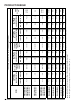
TEMPERATURE RISE 10 20 30 40 50 60 70 30 80 90 100 40 50 60 700 600 CFM 90 100 2000 2200 2400 CFM 1800 1600 1400 OUTPUT BTU/HR x 1000 80 1200 1100 1000 900 70 800 FORMULAS 110 120 130 140 BTU OUTPUT = CFM x 1.08 x RISE BTU OUTPUT RISE = ÷ CFM 1.
WIRING DIAGRAMS *CVC9/*MVC95_AA HIGH VOLTAGE! DISCONNECT ALL POWER BEFORE SERVICING OR INSTALLING THIS UNIT. MULTIPLE POWER SOURCES MAY BE PRESENT. FAILURE TO DO SO MAY CAUSE PROPERTY DAMAGE, PERSONAL INJURY OR DEATH. TO 115 VAC/ 1 Ø /60 HZ POWER SUPPLY WITH OVERCURRENT PROTECTION DEVICE GND 24V HUM.
WIRING DIAGRAMS *CVC9/*MVC95_AB HIGH VOLTAGE! DISCONNECT ALL POWER BEFORE SERVICING OR INSTALLING THIS UNIT. MULTIPLE POWER SOURCES MAY BE PRESENT. FAILURE TO DO SO MAY CAUSE PROPERTY DAMAGE, PERSONAL INJURY OR DEATH. TO 115 VAC/1 Ø /60HZ POWER SUPPLYWITH OVERCURRENT PROTECTION DEVICE GND 24V HUM.
SCHEMATICS BK GROUND TO SCROLL HOUSING GND RD RX TX 12V ST4 BK BK LOAD TRANSFORMER BK 2 R C G W 1 W 2 Y1 Y2 O DEHUM DE HUM INDUCTOR COIL (MEDIUM AND LARGE CABINET MODELS ONLY) ANSI Z21.20 AUTOMATIC IGNITION SYSTEM 24VAC 60Hz 0.8 A. MAX. R WH 59-4715 REV.
5-11 8 1 GAS V ALVE DRAIN SWITCH 13 LO HUM 14 HI EAC 1 HL 4 HI 2 RLS DUAL LED DISPLAYS LO 3 INDUCER AUX 10 N/C 3 9 1 15 4 7 COMM STATUS LED VARIABLE SPEED CIRCULATOR 3 PS1 PS2 RS485 COMM μP TX/RX 3 RJ11 DIPSWX 2 12 CNTL μP 8 N/C 6 W1 W2 O 1 2 Y1 R C 4 XFMR DEHUM G Y2 TYPICAL SCHEMATIC ACVC9/AMV95/GCVC9/GMVC95_____X* MODEL FURNACES WR 50C51-289 INTEGRATED IGNITION CONTROL This schematic is for reference only. Not all wiring is as shown above.