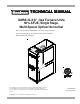
TECHNICAL MANU AL MANUAL GMS8 33-3/8" Gas Furnace Units 80% AFUE, Single Stage, Multi-Speed, Upflow Horizontal • Refer to Service Manual RS6612006 for troubleshooting information. • Refer to the appropriate Parts Catalog for part number information. • Model numbers listed on page 3. This manual is to be used by qualified, professionally trained HVAC technicians only.
PRODUCT IDENTIFICATION The model and manufacturing number are used for positive identification of component parts used in manufacturing. Please use these numbers when requesting service or parts information.
PRODUCT IDENTIFICATION The model and manufacturing number are used for positive identification of component parts used in manufacturing. Please use these numbers when requesting service or parts information. GMS80403A*BB GMS80603A*BB GMS80604B*BB GMS80804B*BB GMS80805C*BB GMS81005C*BB GMS81205D*BA GMS81405DNCC *These models available in Natural Gas and Low NOx.
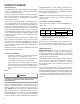
PRODUCT DESIGN General Operation The GMS8 furnaces are equipped with an electronic ignition device used to light the burners and an induced draft blower to exhaust combustion products. An interlock switch prevents furnace operation if the inner blower door is not in place. Keep the blower access door in place except for inspection and maintenance. (See illustration on pages 5 and 6.) This furnace is also equipped with a self-diagnosing electronic control module.
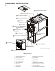
COMPONENT IDENTIFICATION 1 Tubular Heat Exchanger 2 Pressure Switch 3 Flue Pipe Connection 4 Induced Draft Blower ? 5 Gas Line Entrance 6 Gas Valve 7 Rollout Limit 8 Junction Box 9 Wiring Harness Grommet Gas Manifold Gas Line Entrance (Alternate) Inshot Burner Transformer Circulator Blower Blower Door Interlock Switch Note: Primary Limit Not Shown Integrated Control Module Upflow/Horizontal 1 Tubular Heat Exchanger 9 Wiring Harness Grommet 2 Pressure Switch 10 Gas Manifold 3 Flue Pipe Connecti
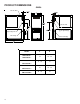
PRODUCT DIMENSIONS GMS8 Alt. Gas Inlet Alt. Gas Inlet Alt. High Voltage High Voltage Inlet Low Voltage Alt.
GMS8[040-100]BB GMS81205D*BA PRODUCT DIMENSIONS GMS81405DNCC P re ssure S w itch Trip P oints Model Trip Point ID Blow er Pressure Sw itch ID Blow er Pressure Sw itch Part # GM S80403A*BB -0.70 B1370158 GM S80603A*BB -0.75 B1370179 GM S80604B*BB -0.75 B1370179 GM S80804B*BB -0.70 B1370158 GM S80805C*BB -0.75 B1370179 GM S81005C*BB -0.70 B1370158 GM S81205D*BA -0.80 0130F00042 GMS81405DNCC -0.
PRODUCT DESIGN Thermostats: It is recommended that a single-stage heat, non-power robbing thermostat be used. Refer to the product marketing literature for a complete list of thermostats offered. THERMOSTATS Filters: Thermostat Man/Auto Programmable Cool Heat Batt. Powered Batt. Bkup 1213406* Man. Or Auto Yes 2 3 No No 1213407 Man. Changeover Yes 2 2 Yes Yes 1213411 Man.
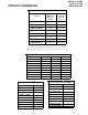
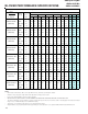
GMS8[040-100]BB GMS81205D*BA FURNACE SPECIFICATIONS Tem perature Rise (°F) GMS80805C*BB GMS81005C*BB GMS81205D*BA GMS81405DNCC Rated External Static (" w.c.) GMS80804B*BB A.F.U.E. GMS80604B*BB O utput (US) High Fire GMS80603A*BB Btuh Input (US) High Fire GMS80403A*BB M O DEL GMS81405DNCC 40,000 60,000 60,000 80,000 80,000 100,000 120,000 140,000 32,000 48,000 48,000 64,000 64,000 80,000 96,000 112,000 80% 80% 80% 80% 80% 80% 80% 80% .20 - .50 .20 - .50 .20 - .50 .
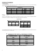
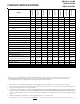
GMS8[040-100]BB GMS81205D*BA BLOWER PERFORMANCE SPECIFICATIONS GMS81405DNCC (CFM & Te m pe ra ture Rise vs. Ex te rna l S ta tic P re ssure ) Model Heating Speed A s Shipped EXTER N AL STATIC PR ESSUR E (Inches Water C olum n ) Ton s AC Motor Spe ed at 0 .5 " 0.1 0 .2 0.3 0.4 0 .5 0 .6 0 .7 0.8 ESP C FM R ISE C FM R ISE C FM R ISE CFM R ISE C FM R ISE C FM CFM CFM H IGH 3 .0 1 52 1 ---- 146 6 ---- 14 14 ---- 1 37 3 ---- 129 8 ---- 12 43 1 164 1 07 5 *MS8 04 03A*BB MED 2 .
TEMPERATURE RISE 10 20 30 40 50 60 70 30 80 90 100 40 50 60 700 600 CFM 90 100 2000 2200 2400 CFM 1800 1600 1400 OUTPUT BTU/HR x 1000 80 1200 1100 1000 900 70 800 FORMULAS 110 120 130 140 BTU OUTPUT = CFM x 1.
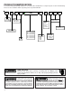
WIRING DIAGRAMS GMS8 WARNING:DISCONNECT POWER BEFORE SERVICING.WIRING TO UNIT MUST BE PROPERLY POLARIZED AND GROUNDED.
SCHEMATICS GMS8 HIGH VOLTAGE! DISCONNECT ALL POWER BEFORE SERVICING OR INSTALLING THIS UNIT. MULTIPLE POWER SOURCES MAY BE PRESENT. FAILURE TO DO SO MAY CAUSE PROPERTY DAMAGE, PERSONAL INJURY OR DEATH. CIRCULATOR BLOWER INDUCER CIR PARK PARK NEU HEAT COOL IND R K2 RO2 RO1 TH K3 K1 ROLLOUT SWITCH XFMR HOT 24 VAC .