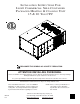
INSTALLATION INSTRUCTIONS FOR LIGHT COMMERCIAL SELF-CONTAINED PACKAGED HEATING & COOLING UNIT 15 & 20 TON CPC ® US C RECOGNIZE THIS SYMBOL AS A SAFETY PRECAUTION. ATTENTION INSTALLING PERSONNEL Prior to installation, thoroughly familiarize yourself with this Installation Manual. Observe all safety warnings. During installation or repair, caution is to be observed. It is your responsibility to install the product safely and to educate the customer on its safe use.
REPLACEMENT PARTS Index Replacement Parts ........................................................ 2 ORDERING PARTS When reporting shortages or damages, or ordering repair parts, give the complete unit model and serial numbers as stamped on the unit’s nameplate. Safety Instructions ........................................................ 2 General Information ...................................................... 3 Unit Location .................................................................
Obtain from: WARNING American National Standards Institute 1430 Broadway New York, NY 10018 System design and installation should also, where applicable, follow information presented in accepted industry guides such as the ASHRAE Handbooks. The manufacturer assumes no responsibility for equipment installed in violation of any code or regulation.
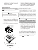
UNIT LOCATION GROUND LEVEL INSTALLATIONS ONLY: • When the unit is installed on the ground adjacent to WARNING TO PREVENT POSSIBLE EQUIPMENT DAMAGE, PROPERTY DAMAGE, PERSONAL INJURY OR DEATH, THE FOLLOWING BULLET POINTS MUST BE OBSERVED WHEN INSTALLING THE UNIT. • IMPORTANT NOTE: Remove wood shipping rails prior to installation of the unit. See important note under Roof Curb Installation Only.
• Do not skid or slide on any surface as this may damage unit base. The unit must be stored on a flat, level surface. Protect the condenser coil because it is easily damaged. 3. Lift unit per the “Rigging Details” section of this manual, observing all warnings and cautions. When unit is lifted, boards and shipping brace will drop if screws have been removed. To avoid injury, STAND CLEAR. 4. Dispose of the boards and brace appropriately.
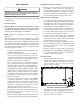
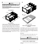
CAUTION ALL CURBS LOOK SIMILAR. TO AVOID INCORRECT CURB POSITIONING, CHECK JOB PLANS CAREFULLY AND VERIFY MARKINGS ON CURB ASSEMBLY. INSTRUCTIONS MAY VARY IN CURB STYLES AND SUPERSEDES INFORMATION SHOWN . See the manual shipped with the roof curb for assembly and installation instructions. CLEARANCES 36”; minimum roof overhang Insulated Panels UNIT CLEARANCES Adequate clearance around the unit should be kept for safety, service, maintenance, and proper unit operation.
RIGGING DETAILS WARNING TO PREVENT PROPERTY DAMAGE, THE UNIT SHOULD REMAIN IN AN UPRIGHT POSITION DURING ALL RIGGING AND MOVING OPERATIONS. TO FACILITATE LIFTING AND MOVING WHEN A CRANE IS USED, PLACE THE UNIT IN AN ADEQUATE CABLE SLING. CAUTION DO NOT LIFT UNITS TWO AT A TIME. PROVISIONS FOR FORKS HAVE BEEN INCLUDED IN THE UNIT BASE FRAME. MINIMUM FORK LENGTH IS 72” TO PREVENT DAMAGE TO THE UNIT. Provisions for forks have been included in the unit base frame. No other fork locations are approved.
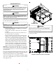
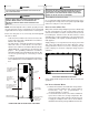
CPC Weights (lbs) CPC Weights (lbs) 15 Tons 20 Tons Corner Weight - A 580 655 Corner Weight - B 540 535 Corner Weight - C 475 510 Corner Weight - D 440 420 Unit Shipping Weight 2150 2235 Unit Operating Weight 2035 2120 X (Inches) 60" 58" Y (Inches) 43" 40" DATA WARNING HIGH VOLTAGE! TO AVOID PERSONAL INJURY OR DEATH DUE TO ELECTRICAL SHOCK, DO NOT TAMPER WITH FACTORY WIRING.
CAUTION WARNING TO AVOID PROPERTY DAMAGE OR PERSONAL INJURY DUE TO FIRE, USE FAILURE OF UNIT DUE TO OPERATION ON IMPROPER LINE VOLTAGE OR WITH EXCESSIVE PHASE UNBALANCE CONSTITUTES PRODUCT ABUSE AND WILL VOID YOUR WARRANTY AND MAY CAUSE SEVERE DAMAGE TO THE UNIT ELECTRICAL COMPONENTS. ONLY COPPER CONDUCTORS. CAUTION Areas Without Convenience Outlet LABEL ALL WIRES PRIOR TO DISCONNECTION WHEN SERVICING CONTROLS. WIRING ERRORS CAN CAUSE IMPROPER AND DANGEROUS OPERATION.
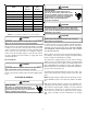
3. Use #18 AWG wire for 24V control wiring runs not exceeding 75 feet. Use #16 AWG wire for 24V control wiring runs not exceeding 125 feet. Use #14 AWG wire for 24V control wiring runs not exceeding 200 feet. Low voltage wiring may be National Electrical Code (NEC) Class 2 where permitted by local codes. 4. Route thermostat wires from sub-base terminals to the unit. Control wiring should enter through the duct panel (dimple marks entrance location).
PRE-STARTUP INSTRUCTIONS TOOLS REQUIRED Refrigeration gauge and manifold Voltmeter Clamp-on ammeter Ohmmeter Test lead (Minimum #16 AWG with insulated alligator clips) Air temperature measuring device General refrigeration mechanics’ tools CAUTION TO PREVENT PROPERTY DAMAGE OR PERSONAL INJURY, DO NOT START THE UNIT UNTIL ALL NECESSARY PRE-CHECKS AND TESTS HAVE BEEN PERFORMED. Prior to the beginning of Startup, Adjustments, and Checks procedures, the following steps should be completed in the building.
System Voltage - That nominal voltage value assigned to a circuit or system for the purpose of designating its voltage class. Nameplate Voltage - That voltage assigned to a piece of equipment for the purpose of designating its voltage class and for the purpose of defining the minimum and maximum voltage at which the equipment will operate. Utilization Voltage - The voltage of the line terminals of the equipment at which the equipment must give fully satisfactory performance.
11. Check for air leaks in the ductwork. See Sections on Air Flow Adjustments. 12. Make sure the unit is free of “rattles”, and the tubing in the unit is free from excessive vibration. Also make sure tubes or lines are not rubbing against each other or sheet metal surfaces or edges. If so, correct the trouble. 13. Set the thermostat at the appropriate setting for cooling and heating or automatic change over for normal use. 14.
MOTOR SHEAVE ADJUSTMENTS CAUTION VL, VM & 2VP VARIABLE PITCH KEY TYPE MOTOR SHEAVES SHEET METAL PARTS, SCREWS, CLIPS AND SIMILAR ITEMS INHERENTLY HAVE SHARP EDGES, AND IT IS NECESSARY THAT THE INSTALLER AND SERVICE PERSONNEL EXERCISE CAUTION. The driving and driven motor sheaves should be in alignment with each other and the shafts parallel. Your Self Contained Packaged Air Conditioner and Heat Pump should operate for many years without excessive service calls if the unit is installed properly.
CLEAN OUTSIDE COIL (QUALIFIED SERVICER ONLY) OUTSIDE AIR INTO RETURN DUCT The coil with the outside air flowing over it should be inspected annually and cleaned as frequently as necessary to keep the finned areas free of lint, hair and debris. Do not introduce cold outside air into the return duct of a heat pump installation. Do not allow air entering the indoor coil to drop below 65° F.
APPENDIX A BLOWER PERFORMANCE DATA BELT DRIVE - STANDARD CPC180 STANDARD BELT DRIVE TURNS OPEN ESP, In H2 O 0 1 2 3 4 5 6 CFM BHP CFM BHP CFM BHP CFM BHP CFM BHP CFM BHP CFM BHP 0.2 --- --- --- --- --- --- --- --- --- --- 7203 2.18 6718 1.94 0.4 --- --- --- --- --- --- 7306 2.54 6777 2.14 6257 1.80 5711 1.66 0.6 --- --- 7477 2.97 6899 2.51 6323 2.10 5716 1.72 5103 1.39 0.8 7112 2.96 6467 2.46 5795 2.01 5101 1.
APPENDIX A BLOWER PERFORMANCE DATA BELT DRIVE - HIGH STATIC CPC180 HIGH STATIC BELT DRIVE TURNS OPEN ESP, In H2 O 0 1 2 3 4 5 6 CFM BHP CFM BHP CFM BHP CFM BHP CFM BHP CFM BHP CFM BHP 1.0 --- --- --- --- --- --- --- --- --- --- 7120 3.26 6223 2.55 1.2 --- --- --- --- --- --- --- --- 6927 3.39 5924 2.61 --- --- 1.4 --- --- --- --- --- --- 6739 3.52 5602 2.65 --- --- --- --- 1.6 --- --- --- --- 6587 3.69 5245 2.
APPENDIX B ELECTRICAL DATA ELECTRICAL DATA MODELS 15 TON VOLTAGE (NAMEPLATE) LARGER COMPRESSOR VOLTAGE LIMITATIONS RLA LRA OD FAN MOTORS (ea) SMALLER COMPRESSOR MIN MAX Qty Qty 208/230-60-3 187 253 1 29.5 195.0 1 460-60-3 414 506 1 14.7 95.0 575-60-3 518 633 1 12.2 80.0 RLA LRA Qty HP RLA 25.0 164.0 3 1/3 2.40 1 12.2 100.0 3 1/3 1 9.0 3 1/3 78.0 ID FAN MOTOR ID MOTOR APPL HP FLA BD STD STATIC 3.0 9.2 1.20 BD STD STATIC 3.0 4.6 0.
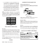
APPENDIX C UNIT DIMENSIONS Model A B C D 15 Ton 20 Ton 133-1/2" 88-7/32" 50-9/32" 5-5/32" B A C D 21” 60” 7” 48” 22” VERTICAL DISCHARGE (TOP VIEW) 19
© 2010 Goodman Manufacturing Company, L.P. 5151 San Felipe, Suite 500 Houston, TX 77056 www.goodmanmfg.com www.amana-hac.