INSTALLATION INSTRUCTIONS FOR LIGHT COMMERCIAL SELF-CONTAINED PACKAGED HEATING & COOLING UNIT 3 TON - 6 TON CPC/CPH SERIES RECOGNIZE THIS SYMBOL AS A SAFETY PRECAUTION. ATTENTION INSTALLING PERSONNEL Prior to installation, thoroughly familiarize yourself with this Installation Manual. Observe all safety warnings. During installation or repair, caution is to be observed. It is your responsibility to install the product safely and to educate the customer on its safe use.
Index REPLACEMENT PARTS Replacement Parts ........................................................ 2 ORDERING PARTS Safety Instructions ........................................................ 2 When reporting shortages or damages, or ordering repair parts, give the complete unit model and serial numbers as stamped on the unit’s nameplate. General Information ...................................................... 3 Unit Location .................................................................
NATIONAL CODES WARNING This product is designed and manufactured to permit installation in accordance with National Codes. It is the installer’s responsibility to install the product in accordance with National Codes and/or prevailing local codes and regulations. THIS UNIT MUST NOT BE USED AS A “CONSTRUCTION HEATER” DURING THE FINISHING PHASES OF CONSTRUCTION ON A NEW STRUCTURE.
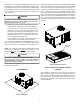
NOTE: When inspecting the unit for transportation damage, remove all packaging materials. Recycle or dispose of the packaging material according to local codes. • Allow minimum clearances from the enclosure for fire PRE-INSTALLATION CHECKS • Carefully read all instructions for the installation prior to installing unit. Ensure each step or procedure is understood and any special considerations are taken into account before starting installation.
Full perimeter roof curbs are available from the factory and are shipped unassembled. Field assembly, squaring, leveling and mounting on the roof structure are the responsibility of the installing contractor. All required hardware necessary for the assembly of the sheet metal curb is included in the curb accessory. Adequate clearance around the unit should be kept for safety, service, maintenance, and proper unit operation.
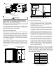
PROTRUSION RIGGING DETAILS Inspect curb to ensure that none of the utility services (electric) routed through the curb protrude above the curb. WARNING TO PREVENT PROPERTY DAMAGE, THE UNIT SHOULD REMAIN IN AN UPRIGHT POSITION DURING ALL RIGGING AND MOVING OPERATIONS. TO FACILITATE CAUTION LIFTING AND MOVING WHEN A CRANE IS USED, PLACE THE UNIT IN AN ADEQUATE CABLE SLING. IF PROTRUSIONS EXIST, DO NO ATTEMPT TO SET UNIT ON CURB.
Lower unit carefully onto roof mounting curb. While rigging unit, center of gravity will cause condenser end to be lower than supply air end.
All line voltage connections must be made through weatherproof fittings. All exterior power supply and ground wiring must be in approved weatherproof conduit. CAUTION TO PREVENT SEVERE DAMAGE TO THE BOTTOM OF THE UNIT, DO NOT FORK LIFT UNIT AFTER WOOD STRUTS HAVE BEEN REMOVED .
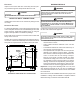
MAIN POWER LOW VOLTAGE BLOCK RETURN LOW VOLTAGE ENTRANCE SUPPLY 3.5 DIA. POWER THRU THE CURB 41/2” POWER THRU THE CURB CONTROL BOX 47 1/2” WARNING FAILURE OF UNIT DUE TO OPERATION ON IMPROPER LINE VOLTAGE OR WITH EXCESSIVE PHASE UNBALANCE CONSTITUTES PRODUCT ABUSE AND WILL VOID YOUR WARRANTY AND MAY CAUSE SEVERE DAMAGE TO THE UNIT ELECTRICAL COMPONENTS. LOW VOLTAGE CONTROL WIRING 1. A 24V thermostat must be installed for unit operation. It may be purchased with the unit or field -supplied.
CIRCULATING AIR AND FILTERS STARTUP, ADJUSTMENTS, AND CHECKS DUCTWORK WARNING The supply duct from the unit through a wall may be installed without clearance. However, minimum unit clearances must be maintained (see “Clearances” section). The supply duct should be provided with an access panel large enough to inspect the air chamber downstream of the heat exchanger. A cover should be tightly attached to prevent air leaks.
TOOLS REQUIRED System Voltage - That nominal voltage value assigned to a circuit or system for the purpose of designating its voltage class.
ing and clamps. The entire refrigeration system has been factory charged and tested, making it unnecessary to field charge. Factory charges are shown on the unit nameplate. Install service manifold hoses. Gauges should read saturation pressure corresponding to ambient temperature. Charge should be checked to obtain 12° to 15° of sub-cooling per system (i.e. compressor circuits). START-UP PROCEDURE AND CHECKLIST Begin with power turned off at all disconnects. 1.
REFRIGERATION PERFORMANCE CHECK 11. Slowly raise the heating temperature setting. When the heating first stage makes contact, stop raising the temperature setting.. The compressor, blower and fan should now be running with the reversing valve in the de-energized (heating) position. After giving the unit time to settle out, make sure the unit is supplying heated air. 12. If the outdoor ambient is above 80°F, the unit may trip on its high pressure cut out when on heating. The compressor should stop.
DEFROST CONTROL C O O LIN G S E RV IC E P O RT R E V E RS IN G V A LV E During operation the power to the circuit board is controlled by a temperature sensor, which is clamped to a feeder tube entering the outdoor coil. Defrost timing periods of 30,60 and 90 minutes may be selected by setting the circuit board jumper to 30, 60 and 90 respectively. Accumulation of time for the timing period selected starts when the sensor closes (approximately 31° F), and when the wall thermostat calls for heat.
DRIVE ADJUSTMENTS MOTOR SHEAVE ADJUSTMENTS CAUTION SHEET METAL PARTS, SCREWS, CLIPS AND SIMILAR ITEMS INHERENTLY HAVE SHARP EDGES, AND IT IS NECESSARY THAT THE INSTALLER AND SERVICE PERSONNEL EXERCISE CAUTION. VL, VM, & 2VP VARIABLE PITCH KEY TYPE MOTOR SHEAVES The driving and driven motor sheaves should be in alignment with each other and the shafts parallel.
LUBRICATION UNDERCHARGE The fan shaft bearings, the 1 to 2 HP supply fan motors the condenser fan motors and compressors are permanently lubricated. An undercharged heat pump on the heating cycle will cause low discharge pressure resulting in low suction pressure and frost accumulation on the outdoor coil. FUNCTIONAL PARTS POOR “TERMINATING” SENSOR CONTACT Refer to the unit Parts Catalog for a list of functional parts. Parts are available from your distributor.
APPENDIX A BLOWER PERFORMANCE TABLES DIRECT DRIVE STANDARD DOWN SHOT AND HORIZONTAL CPC/H036 DIRECT DRIVE DOWN SHOT SPEED TAP EXTERNAL STATIC PRESSURE (ESP) in w.c. STAN DARD CFM AMPS WATTS RPM LOW 0.10 0.20 0.30 0.40 0.50 0.60 1287 1233 1176 1107 1044 965 1.66 1.63 1.59 1.55 1.51 1.45 350 342 332 320 312 296 770 815 858 891 924 957 MED 0.10 0.20 0.30 0.40 0.50 0.60 0.70 1476 1421 1334 1255 1180 1085 964 2.08 2.03 1.96 1.90 1.84 1.78 1.
APPENDIX A BLOWER PERFORMANCE TABLES DIRECT DRIVE STANDARD DOWN SHOT AND HORIZONTAL CPC/H048 DIRECT DRIVE DOWN SHOT SPEED TAP EXTERNAL STATIC PRESSURE (ESP) in w.c. STAN DARD CFM AMPS WATTS RPM LOW 0.10 0.20 0.30 0.40 0.50 1602 1538 1474 1390 1306 2.48 2.37 2.26 2.15 2.04 528 506 484 460 436 835 878 921 950 979 MED 0.10 0.20 0.30 0.40 0.50 0.60 0.70 1805 1704 1625 1549 1437 1301 1158 2.84 2.71 2.59 2.47 2.38 2.23 2.09 620 590 558 540 516 480 444 935 967 990 1012 1030 1050 1072 HIGH 0.
APPENDIX A BLOWER PERFORMANCE TABLES DIRECT DRIVE STANDARD CPC/H060 DOWN SHOT CPC/H060 DIRECT DRIVE DOWN SHOT SPEED TAP EXTERNAL STATIC PRESSURE (ESP) in w.c. STANDARD C FM AMPS WATTS RPM T1 0.10 0.20 0.30 0.40 0.50 0.60 0.70 0.80 0.90 1334 1286 1212 1144 1077 1039 953 904 825 1.65 1.75 1.83 1.94 1.99 2.10 2.17 2.27 2.30 180 192 202 216 222 238 248 258 266 627 665 715 759 792 830 874 913 940 T2 0.10 0.20 0.30 0.40 0.50 0.60 0.70 0.80 0.90 1512 1469 1397 1333 1285 1221 1173 1118 1049 2.12 2.
APPENDIX A BLOWER PERFORMANCE TABLES DIRECT DRIVE STANDARD CPC/H060 HORIZONTAL CPC/H060 DIRECT DRIVE HORIZONTAL SPEED TAP EXTERNAL STATIC PRESSURE (ESP) in w.c. STANDAR D CFM AMPS WATTS RPM T1 0.10 0.20 0.30 0.40 0.50 0.60 0.70 0.80 0.90 1355 1281 1235 1168 1118 1049 982 922 871 1.57 1.66 1.76 1.81 1.94 2.03 2.10 2.14 2.25 174 182 196 202 218 232 240 246 260 599 651 693 726 775 819 858 885 927 T2 0.10 0.20 0.30 0.40 0.50 0.60 0.70 0.80 0.90 1544 1490 1427 1370 1319 1274 1210 1137 1106 2.04 2.
APPENDIX A BLOWER PERFORMANCE TABLES BELT DRIVE STANDARD DOWN SHOT CPC/H036 STANDARD BELT DRIVE DOWN SHOT ESP, In H 2O TURNS OPEN 0 CFM 1 BHP CFM 2 BHP 3 4 BHP CFM BHP CFM 1520 0.39 1292 0.29 944 0.21 619 0.12 0.2 0.4 1439 0.40 1192 0.30 0.8 1350 0.42 1101 0.31 864 0.22 1.0 1028 0.31 729 0.21 1.2 675 0.20 0.6 5 CFM BHP CFM BHP 1424 0.30 1239 0.23 1073 0.22 779 0.
APPENDIX A BLOWER PERFORMANCE TABLES BELT DRIVE HIGH STATIC DOWN SHOT CPC/H036 HIGH STATIC BELT DRIVE DOWN SHOT ESP, In H 2O TURNS OPEN 0 CFM 1 BHP CFM 2 BHP 3 CFM 1692 0.54 1678 0.58 1397 0.44 1078 0.34 794 0.22 1681 0.65 1381 0.49 1.2 1681 0.71 1362 0.54 1062 0.39 1.4 1362 0.60 1066 0.44 1.6 1066 0.50 789 0.34 1.8 789 0.40 1.0 BHP CFM 5 BHP 0.6 0.8 4 CFM BHP CFM BHP 1449 0.41 1173 0.29 1107 0.31 854 0.
APPENDIX A BLOWER PERFORMANCE TABLES BELT DRIVE STANDARD HORIZONTAL CPC/H036 STANDARD BELT DRIVE HORIZONTAL ESP, In H 2O TURNS OPEN 0 CFM 1 BHP CFM 2 BHP CFM 3 BHP CFM 4 BHP 0.2 0.4 0.6 0.8 1.0 1581 1266 0.50 0.39 1.2 923 0.28 5 CFM BHP CFM 1658 0.35 1489 0.28 1129 0.21 1560 0.36 1339 0.28 949 0.19 1682 0.47 1436 0.36 1196 0.27 1354 994 0.38 0.28 1096 756 0.28 0.19 828 0.
APPENDIX A BLOWER PERFORMANCE TABLES BELT DRIVE HIGH STATIC HORIZONTAL CPC/H036 HIGH STATIC BELT DRIVE HORIZONTAL ESP, In H 2O TURNS OPEN 0 CFM 1 BHP CFM 2 BHP CFM 3 BHP CFM 4 BHP 0.6 0.8 1 1.2 0.68 1605 1281 0.62 0.51 1281 0.57 981 0.41 981 0.47 1.4 1605 1.6 1.8 5 CFM BHP CFM BHP 1742 0.50 1431 0.36 1078 0.27 1626 0.52 1357 0.39 1611 0.56 1315 0.42 1011 0.28 1299 959 0.46 0.35 976 0.
APPENDIX B ELECTRICAL DATA ELECTRICAL DATA MODELS VOLTAGE (NAMEPLATE) VOLTAGE LIMITATION OUTDOOR FAN MOT OR COMPRESSOR MIN. MAX. QTY RLA LRA QTY HP RLA 208/230-60-1 187 253 1 16.67 79 1 1/4 1.40 208/230-60-3 187 253 1 10.45 73.0 1 1/4 1.40 3 TON INDOOR FAN MOTOR HP FLA DD STD STATIC 1/3 2.5 DD STD STATIC 1/3 2.5 BD STD STATIC 1.0 3.8 460-60-3 414 506 1 5.77 38.0 1 1/4 0.80 BD STD STATIC 1.0 1.9 575-60-3 518 633 1 3.8 37.0 1 1/4 0.
APPENDIX B ELECTRICAL DATA MINIMUM AIR FLOW FOR ELECTRIC HEAT UNIT 3 TON 4 TON 5 TON 6 TON HEATER KIT MOD EL N UMBER MINIMUM CFM EHK*-10 1250 EHK*-15 1250 EHK*-10 1300 EHK*-15 1400 EHK*-18 1400 EHK*-10 1700 EHK*-15 1700 EHK*-20 1800 EHK*-10 2100 EHK*-15 2100 EHK*-20 2100 EHK*-25 2100 ATTENTION INSTALLING PERSONNEL Use only the heater kit specified for each model as dictated by the table above.
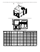
APPENDIX C UNIT DIMENSIONS 47 1/2” 73 1/4” 38 13/16”* 74 1/16” *6 Ton - 42 13/16 48 3/16” 11” 17” 7 3/8” RETURN 12” 4 7/8” 25” 19 7/16” SUPPLY RETURN DRAIN THRU CURB LOCATION 5 7/8” 6 1/4” EMBOSS FOR THRU THE BASE UTILITIES SUPPLY HORIZONTAL DISCHARGE 27 3/8” 4 1/2” NOTE For horizontal discharge, remove the supply and return duct covers and place them over the vertical discharge return and supply openings.
Goodman Manufacturing Company, L.P. 5151 Felipe, Suite 500, Houston, TX 77056 www.goodmanmfg.com www.amana-hac.com © 2010,2012 Goodman Manufacturing Company, L.P.