Service Instructions Split System Air Conditioners, Split System Heat Pumps with R-22 Refrigerant Blowers, Coils, & Accessories This manual is to be used by qualified, professionally trained HVAC technicians only. Goodman does not assume any responsibility for property damage or personal injury due to improper service procedures or services performed by an unqualified person. Copyright © 2005 - 2009 Goodman Manufacturing Company, L.P.
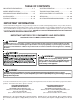
TABLE OF CONTENTS IMPORTANT INFORMATION ......................... 2 - 3 SYSTEM OPERATION .............................. 23 - 27 MODEL IDENTIFICATION ............................ 4 - 15 TROUBLESHOOTING CHART ......................... 28 AIR HANDLER/COIL IDENTIFICATION ............ 15 SERVICING TABLE OF CONTENTS ................ 29 ACCESSORIES ......................................... 16 - 20 SERVICING ................................................. 30 - 60 PRODUCT DESIGN ...........................
IMPORTANT INFORMATION SAFE REFRIGERANT HANDLING While these items will not cover every conceivable situation, they should serve as a useful guide. WARNING Refrigerants are heavier than air. They can "push out" the oxygen in your lungs or in any enclosed space.To avoid possible difficulty in breathing or death: • Never purge refrigerant into an enclosed room or space. By law, all refrigerants must be reclaimed. • If an indoor leak is suspected, thoroughly ventilate the area before beginning work.
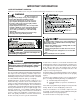
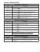
PRODUCT IDENTIFICATION Split System Air Conditioners R-22 Model # Description GSC13018-241AA Goodman® Brand Split Condenser 13 Seer condensing units. Initial release. 26" chassis GSC13036-481AA G oodman® Brand Split Condenser 13 Seer condensing units. Initial release. 29" chassis GSC13036,48*AA Goodman® Brand Split Condenser 13 Seer condensing units. Introduces new 13 SEER AC 3 PH R-22 Goodman Models GSC130**1AB Goodman® Brand Split Condenser 13 Seer condensing units. Move location of screw hole.
PRODUCT IDENTIFICATION Split System Air Conditioners R-22 Model # Description GSC140**1AA Goodman® Brand Split Condenser 14 Seer condensing units. Introduces Goodman® Brand 14 Seer AC R-22 models. GSC140**1AB Goodman® Brand Split Condenser 14 Seer condensing units. New revisions have screw locations moved in the top panel, base pans, louvers, and control box covers. GSC140**1AC Goodman® Brand Split Condenser 14 Seer condensing units.
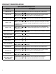
PRODUCT IDENTIFICATION Split System Heat Pumps R-22 Model # GSH10***AA Goodman® Brand Split Heat Pump 10 Seer heat pump units. Initial release. GSH10***AB Goodman® Brand Split Heat Pump 10 Seer heat pump units. Screw locations moved in the top panel, base pans, louvers, and control box covers. . GSH13***AA Goodman® Brand Split Heat Pump 13 Seer heat pump units. Initial release. GSH13**1AB Goodman® Brand Split Heat Pump 13 Seer heat pump units.
PRODUCT IDENTIFICATION Split System Heat Pumps R-22 Model # Description ASH130**1AA Amana® Brand Split Heat Pump 13 Seer heat pump units. Initial release new models of Amana® Brand Deluxe 13 Seer R-22 heat pumps. ASH130**1AB Amana® Brand Split Heat Pump 13 Seer heat pump units. New revisions have screw locations moved in the top panel, base pans, louvers, and control box covers. ASH130**1AC Amana® Brand Split Heat Pump 13 Seer heat pump units. New revisions have horizontal style louvers.
PRODUCT IDENTIFICATION Single Piece Air Handlers Model # ARUF****16AA A Single Piece R Multi-Position PSC Motor Unpainted Flowrater Introduction of new 13 SEER Air Handler Models. All Models will be suitable for use with R-22 and R-410A ARUF364216AB A Single Piece R Multi-Position PSC Motor Unpainted Flowrater.Revision replaces the current spot welded blower housing with the same cinched or crimped design used on the 80% furnace line.
PRODUCT IDENTIFICATION Single Piece Air Handlers Model # Description AEPF****16AA A Single Piece E Multi-Position Variable-Speed Painted Flowrator. Introducation of new 13 SEER Air Handler Models. All Models will be suitable for use with R-22 and R-410A AEPF****16BA A Single Piece E Multi-Position Variable-Speed Painted Flowrator. Revision introduces new models adding lower kw hit kits on the S&R plate AEPF****16BB A Single Piece E Multi-Position Variable-Speed Painted Flowrator.
PRODUCT IDENTIFICATION MBR/MBE Air Handlers Model # Description MBR****AA-1AA Modular Blower R Multi-Position PSC Motor. Introduces module blower with PSC blower motor. MBE****AA-1AA M odular Blower E Multi-Position Variable-Speed. Introduces module blower with variable speed blower motor. MBE****AA-1BA Modular Blower E Multi-Position Variable-Speed.
PRODUCT IDENTIFICATION G S C BRAND: ® G: Goodman Brand / Amana® Brand Distinctions ® A: Amana Brand V: Value 14 036 UNIT TYPE: C: Condenser R-22 H: Heat Pump R-22 A A MINOR REVISION: A: Initial Release SEER: 10: 10 SEER 13: 13 SEER 14: 14 SEER PRODUCT CATEGORY: S: Split System 1 MAJOR REVISION: A: Initial Release NOMINAL CAPACITY: 018: 1.5 Tons 024: 2 Tons 030: 2.5 Tons 036: 3 Tons 042: 3.
PRODUCT IDENTIFICATION C KF 036 2 REVISION: A: Revision PRODUCT CATEGORY: C: Split System 1: 2: 3: 4: UNIT TYPE: E: Commercial Air Conditioner K: Air Cojditioner P: Heat Pump 018: 024: 030: 036: 042: C ELECTRICAL: 208-230V/1ph/60Hz 220-240V/1ph/50 Hz 208-230v/3ph/60Hz 308/415V/3ph/50Hz NOMINAL CAPACITY: 1.5 Tons 048: 4 Tons 2 Tons 060: 5 Tons 2.5 Tons 070: 5 Tons 3 Tons 090: 7.5 Tons 3.
PRODUCT IDENTIFICATION C E 120 5 A REVISION: A: Revision PRODUCT CATEGORY: C: Split System 1: 2: 3: 4: UNIT TYPE: E: Commercial Air Conditioner K: Air Cojditioner P: Heat Pump ELECTRICAL: 208-230V/1ph/60Hz 220-240V/1ph/50 Hz 208-230v/3ph/60Hz 308/415V/3ph/50Hz NOMINAL CAPACITY: 018: 1.5 Tons 048: 4 Tons 024: 2 Tons 060: 5 Tons 030: 2.5 Tons 070: 5 Tons 036: 3 Tons 090: 7.5 Tons 042: 3.
PRODUCT IDENTIFICATION THIS NOMENCLATURE IS TO BE USED AFTER JULY 2006 A W PRODUCT TYPE: A: Air Handler U F 3642 1 6 EXPANSION DEVICE: F: Flowrater T: TXV (Expansion Device) A MINOR REVISION* MAJOR REVISION* CABINET FINISH: U: Unpainted P: Paited N: Uncased APPLICATION C: Ceiling Mount PSC Motor D: Downflow PSC Motor E: Multi-Position Varible-Speed Motor S: Energy-Efficient Motor R: Multi-Position PSC Motor T: Coated Coils W: Wall Mount PSC Motor A REFRIGERANT CHARGE: No Digit: R-22 Only 6: R
PRODUCT IDENTIFICATION C A P F 1824 A 6 A EXPANSION DEVICE: F: Flowrater PRODUCT TYPE: C: Indoor Coil REVISION A: Revision REFRIGERANT CHARGE: 6: R-410A or R-22 2: R-22 4: R-410a CABINET FINISH: U: Unpainted P: Painted N: Unpainted Case NOMINAL WIDTH FOR GAS FURNACE A: Fits 14" Furnace Cabinet B: Fits 17 1/2" Furnace Cabinet C: Fits 21" Furnace Cabinet D: Fits 24 1/2" Furnace Cabinet N: Does Not Apply (Horizontal Slab Coils) APPLICATION A: Upflow/Downflow Coil H: Horizontal A Coil S: Horizonta
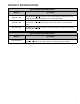
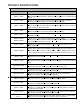
ACCESSORIES Model AFE18-60A OT18-60A FSK01A* ASC01 TX2N2* TX3N2* TX5N2* OT18-60A OT/EHR18-60 Description All Fuel Kit Outdoor Thermostat Freeze Protection Kit Anti Short Cycle Kit X X X X X X X X X X X X X X TXV Kit TXV Kit x x --- --- --- --- X X X ----- ----- ----- --- --- --- X X X X X X X X X X X X X X X X X X X --- --- --- X --- --- X X X X TXV Kit Outdoor Lockout Stat Emergency Heat relay kit CSR-U-1 CSR-U-2 CSR-U-3 Hard Start Kit Hard Start Kit Hard Start Kit
ACCESSORIES Model AFE18-60A Description All Fuel Kit OT18-60A Outdoor Thermostat FSK01A* Freeze Protection Kit ASC01 Anti Short Cycle Kit TX2N2* TXV Kit TX3N2* TXV Kit TX5N2* TXV Kit OT18-60A Outdoor Lockout Stat OT/EHR18-60 Emergency Heat relay kit CSR-U-1 Hard Start Kit CSR-U-2 Hard Start Kit Hard Start Kit CSR-U-3 Model AFE18-60A Description All Fuel Kit OT18-60A Outdoor Thermostat FSK01A* Freeze Protection Kit ASC01 Anti Short Cycle Kit TX2N2* TXV Kit TX3N2* TXV Kit TX
ACCESSORIES EXPANSION VALVE KITS For Applications requiring 1/4 FLARE CONNECTION BULB TO BE LOCATED AT 10 OR 2 O'CLOCK a field installed access fitting BULB SUCTION LINE EVAPORATOR COIL PISTON SEAL SUPPLIED W/ KIT SEAL SUPPLIED W/ KIT SEAL DISTRIBUTOR BODY EXPANSION VALVE TAILPIECE REMOVE BEFORE INSTALLING EXPANSION VALVE 3/8"SWEAT 7/8" NUT For Applications not requiring 1/4' FLARE CONNECTION a field installed access fitting BULB TO BE LOCATED AT 10 OR 2 O'CLOCK BULB SUCTION LINE PISTON EX
ACCESSORIES FSK01A FREEZE THERMOSTAT KIT Wire Nut Y Bl ac k Y k ac Bl Wire Nut Install Line Thermostat Here Install Line Thermostat Here Wire Nut Bla ck Y Bla ck Wire Nut Y ASC01A ANTI-SHORT -CYCLE CONTROL KIT SHORT CYCLE PROTECTOR Y1 R1 Y2 R2 YELLOW 1 CONTACTOR T2 T1 Y BLACK 1 THERMOSTAT WIRE L2 L1 C BLACK 1 UNIT TERMINAL BOARD 19
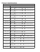
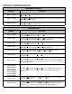
ACCESSORIES COIL ACCESSORIES COIL MODEL TX2N2 TXV KIT TX3N2 TXV KIT TX5N2 TXV KIT FSK01A FREEZE PROTECTION KIT CA*F030B4* --- X --- X CA*F036B4* --- X --- X CA*F042C4* --- --- X X CA*F048C4* --- --- X X CA*F057D4* --- --- X X CA*F060D4* --- --- X X CHPF030A4* --- X --- X CHPF036B4* --- X --- X CHPF042A4* --- --- X X CHPF048D4* --- --- X X CHPF060D4* --- --- X X CH36FCB --- X --- X CH48FCB --- --- X X CH60FCB --- --- X X CA*F18246* X
PRODUCT DESIGN This section gives a basic description of cooling unit operation, its various components and their basic operation. Ensure your system is properly sized for heat gain and loss according to methods of the Air Conditioning Contractors Association (ACCA) or equivalent. CONDENSING UNIT These units are designed for free air discharge. Condensed air is pulled through the condenser coil by a direct drive propeller fan and then discharged from the cabinet top.
PRODUCT DESIGN The coils are designed for upflow, counterflow or horizontal application, using two-speed direct drive motors on the CACF/CAPF/CHPX models and BPM (Brushless Permanent Magnet) or ECM motors on the MBE models. The ARUF is a multi-position air handler (upflow/horizontal or downflow) and is equipped with a flowrator for cooling and heat pump applications. Because of its seamless copper tubing and aluminum fins, there are fewer leaks.
SYSTEM OPERATION COOLING The refrigerant used in the system is R-22. It is a clear, colorless, non-toxic, non-irritating, and non-explosive liquid. The chemical formula is CHCLF2. The boiling point, at atmospheric pressure is -41.4°F. The check valve at the indoor coil will open by the flow of refrigerant letting the now condensed liquid refrigerant bypass the indoor expansion device.
SYSTEM OPERATION COOLING CYCLE Reversing Valve (Energized) Indoor Coil Outdoor Coil Accumulator Thermostatic Expansion Valve Bi-Flow Filter Dryer Check Valve HEATING CYCLE Reversing Valve (De-Energized) Indoor Coil Outdoor Coil Accumulator Thermostatic Expansion Valve Bi-Flow Filter Dryer Check Valve 24
SYSTEM OPERATION EXPANSION VALVE/CHECK VALVE ASSEMBLY IN COOLING OPERATION EXPANSION VALVE/CHECK VALVE ASSEMBLY IN HEATING OPERATION Most expansion valves used in current Amana® Brand Heat Pump products use an internally checked expansion valve. This type of expansion valve does not require an external check valve as shown above. However, the principle of operation is the same.
SYSTEM OPERATION COOLING CYCLE - CONDENSING UNIT Indoor Coil Outdoor Coil Thermostatic Expansion Valve In the cooling mode, the orifice is pushed into its seat, forcing refrigerant to flow through the metered hole in the center of the orifice.
SYSTEM OPERATION AFE18-60A CONTROL BOARD DESCRIPTION The AFE18 control is designed for use in heat pump applications where the indoor coil is located above/downstream of a gas or fossil fuel furnace. It will operate with single and two stage heat pumps and single and two stage furnaces. The AFE18 control will turn the heat pump unit off when the furnace is turned on. An anti-short cycle feature is also incorporated which initiates a 3 minute timed off delay when the compressor goes off.
TROUBLESHOOTING CHART COOLING/HP ANALYSIS CHART Power Failure Blown Fuse Unbalanced Power, 3PH Loose Connection Shorted or Broken Wires Open Fan Overload Faulty Thermostat Faulty Transformer Shorted or Open Capacitor Internal Compressor Overload Open Shorted or Grounded Compressor Compressor Stuck Faulty Compressor Contactor Faulty Fan Relay Open Control Circuit Low Voltage Faulty Evap.
SERVICING TABLE OF CONTENTS S-1 S-2 S-3 S-3A S-3B S-3C S-3D S-4 S-5 S-6 S-7 S-8 S-9 S-10 S-11 S-15 S-15A S-15B S-16A S-16B S-16C S-16D S-16E S-17 S-17A S-17B S-17D S-18 S-21 S-24 S-25 Checking Voltage .......................................... 30 Checking Wiring ............................................ 30 Checking Thermostat, Wiring & Anticipator .. 30 Thermostat & Wiring ..................................... 30 Cooling Anticipator ........................................ 31 Heating Anticipator .......
SERVICING S-2 CHECKING WIRING S-1 CHECKING VOLTAGE 1. Remove outer case, control panel cover, etc., from unit being tested. With power ON: WARNING Line Voltage now present. 2. Using a voltmeter, measure the voltage across terminals L1 and L2 of the contactor for the condensing unit or at the field connections for the air handler or heaters. 3. No reading - indicates open wiring, open fuse(s) no power or etc., from unit to fused disconnect service. Repair as needed. 4.
SERVICING 4. Check the continuity of the thermostat and wiring. Repair or replace as necessary. Resistance Heaters 1. Set room thermostat to a higher setting than room temperature so both stages call for heat. element helping the thermostat call for the next cooling cycle. This prevents the room temperature from rising too high before the system is restarted. A properly sized anticipator should maintain room temperature within 1 1/2 to 2 degree range. 2.
SERVICING S-4 CHECKING TRANSFORMER AND CONTROL CIRCUIT With power ON: WARNING Line Voltage now present. 1. Apply 24 VAC to terminals R1 and R2. 2. Should read 24 VAC at terminals Y1 and Y2. 3. Remove 24 VAC at terminals R1 and R2. 4. Should read 0 VAC at Y1 and Y2. A step-down transformer (208/240 volt primary to 24 volt secondary) is provided with each indoor unit. This allows ample capacity for use with resistance heaters. The outdoor sections do not contain a transformer.
SERVICING S-7 CHECKING CONTACTOR AND/OR RELAYS WARNING HIGH VOLTAGE! Disconnect ALL power before servicing or installing. Multiple power sources may be present. Failure to do so may cause property damage, personal injury or death. T2 T1 CC VOLT/OHM METER L2 The compressor contactor and other relay holding coils are wired into the low or line voltage circuits. When the control circuit is energized, the coil pulls in the normally open contacts or opens the normally closed contacts.
SERVICING S-10 COPELAND COMFORT ALERT™ DIAGNOSTICS Applies to ASC13 & ASH13 Comfort Alert™ is self-contained with no required external sensors and is designed to install directly into the electrical box of any residential condensing unit that has a Copeland Scroll™ compressor inside. Once attached, Comfort Alert™ provides around-the-clock monitoring for common electrical problems, compressor defects and broad system faults.
SERVICING DIAGNOSTICS TABLE Status LED Green “POWER” Red “TRIP” Status LED Description Module has power Status LED Troubleshooting Information Supply voltage is present at module terminals Thermostat demand signal 1. Compressor protector is open Y1 is present, but the 2. Outdoor unit power disconnect is open compressor is not 3. Compressor circuit breaker or fuse(s) is open running 4. Broken wire or connector is not making contact 5. Low pressure switch open if present in system 6.
SERVICING S-11 CHECKING LOSS OF CHARGE PROTECTOR (Heat Pump Models) The loss of charge protector senses the pressure in the liquid line and will open its contacts on a drop in pressure. The low pressure control will automatically reset itself with a rise in pressure. The low pressure control is designed to cut-out (open) at approximately 7 PSIG. It will automatically cut-in (close) at approximately 25 PSIG.
SERVICING B. Shorted - indicator swings to zero and stops there replace. 1. Remove the motor leads from its respective connection points and capacitor (if applicable). C. Open - no reading - replace. (Start capacitor would read resistor resistance.) 2. Check the continuity between each of the motor leads. S-15B CAPACITANCE CHECK Using a hookup as shown below, take the amperage and voltage readings and use them in the formula: 3.
SERVICING } 1 2 Lines 1 and 2 will be connected for 12OVAC Power Connector applications only 3 Gnd 4 AC Line Connection 5 AC Line Connection 4. Using an ohmmeter, check the motor windings for continuity to ground (pins to motor shell). If the ohmmeter indicates continuity to ground, the motor is defective and must be replaced. 5. Using an ohmmeter, check the windings for continuity (pin to pin). If no continuity is indicated, the thermal limit (over load) device may be open.
- Does removing panel or filter reduce "puffing"? - Check/replace filter. - Check/correct duct restrictions. - Adjust to correct blower speed setting. - Incorrect or dirty filter(s). - Incorrect supply or return ductwork. - Incorrect blower speed setting. - Varies up and down or intermittent. - "Hunts" or "puffs" at high CFM (speed). ---- - Check line voltage for variation or "sag". - Check low voltage connections (G, Y, W, R, C) at motor, unseated pins in motor harness connectors.
- Turn power OFF prior to repair. - Check for loose blower housing, panels, etc. - Check for air whistling thru seams in ducts, cabinets or panels. - Check for cabinet/duct deformation. - Does removing panel or filter reduce "puffing"? - Check/replace filter. - Check/correct duct restrictions. - Adjust to correct blower speed setting. - Loose blower housing, panels, etc. - High static creating high blower speed. - Air leaks in ductwork, cabinets, or panels. - High static creating high blower speed.
SERVICING DIPSWITCH FUNCTIONS The MBE air handler motor has an electronic control that contains an eight (8) position dip switch. The function of these dipswitches are shown in Table 1. Dipsw itch Num ber 1 2 3 4 5 6 7 8 Function Electric Heat N/A Indoor Therm ostat Cooling & Heat Pum p CFM CFM Trim Adjust Table 1 CFM DELIVERY Tables 2, 2A and 3, 3A show the CFM output for dipswitch combinations 1-2, 5-6 and 7-8.
SERVICING HUMIDITY CONTROL When using a Humidstat (normally closed), cut jumper PJ6 on the control board. The Humidstat will only affect cooling airflow by adjusting the Airflow to 85%. TWO STAGE HEATING When using staged electric heat, cut jumper PJ4 on the control board. S-16E CHECKING GE X13TM MOTORS The GE X13TM Motor is a one piece, fully encapsulated, 3 phase brushless DC (single phase AC input) motor with ball bearing construction. Unlike the ECM 2.3/2.
SERVICING HI-POT 1. Remove the leads from the compressor terminals. See warnings S-17 before removing compressor terminal cover. 2. Using an ohmmeter, test continuity between terminals SR, C-R, and C-S, on single phase units or terminals T2, T2 and T3, on 3 phase units. COMPRESSOR GROUND TEST 3. If a ground is indicated, then carefully remove the compressor terminal protective cover and inspect for loose leads or insulation breaks in the lead wires. 4.
SERVICING A. If the compressor starts and continues to run, the cause for failure is somewhere else in the system. B. If the compressor fails to start - replace. COPELAND COMPRESSOR 03 A 12345 L YEAR MONTH SER IAL NUMBER PLANT If voltage is registered at the coil, tap the valve body lightly while switching the system from HEATING to COOLING, etc. If this fails to cause the valve to switch positions, remove the coil connector cap and test the continuity of the reversing valve solenoid coil.
SERVICING S-40 AR*F & MBR ELECTRONIC BLOWERS TIME DELAY RELAY The MBR contains an Electronic Blower Time Delay Relay board, B1370735. This board provides on/off time delays for the blower motor in cooling and heat pump heating demands when “G” is energized. During a cooling or heat pump heating demand, 24Vac is supplied to terminal “G” of the EBTDR to turn on the blower motor. The EBTDR initiates a 7 second delay on and then energizes it’s onboard relay.
SERVICING 4.0 Heating Operation On heat pump units, when the room thermostat set to the heating mode, the reversing valve is not energized. As long as the thermostat is set for heating, the reversing valve will be in the de-energized position for heating except during a defrost cycle. Some installations may use one or more outdoor thermostats to restrict the amount of electric heat that is available above a preset ambient temperature.
SERVICING AEP* & MBE WITH SINGLE STAGE CONDENSERS When used with a single stage condenser, dip switch #4 must be set to the on position on the VSTB inside the MBE. The “Y” output from the indoor thermostat must be connected to the yellow wire labeled “Y/Y2” inside the wire bundle marked “Thermostat” and the yellow wire labeled “Y/Y2” inside the wire bundle marked “Outdoor Unit” must be connected to “Y” at the condenser.
SERVICING rate programmed in the motor. 4.0 Heating Operation On heat pump units, when the room thermostat is set to the heating mode, the reversing valve is not energized. As long as the thermostat is set for heating, the reversing valve will be in the de-energized position for heating except during a defrost cycle. Some installations may use one or more outdoor thermostats to restrict the amount of electric heat that is available above a preset ambient temperature.
SERVICING lation. TEMPERATURE RISE (F°) @ 240V Other components such as a Heating/Cooling Thermostat and Outdoor Thermostats are available to complete the installation. The system CFM can be determined by measuring the static pressure external to the unit. The installation manual supplied with the blower coil, or the blower performance table in the service manual, shows the CFM for the static measured.
SERVICING WARNING Disconnect ALL power before servicing. 1. Never open a system that is under vacuum. Air and moisture will be drawn in. 2. Plug or cap all openings. 1. Remove the wiring from the control terminals. 2. Using an ohmmeter, test for continuity across the normally closed contacts. No reading indicates the control is open - replace if necessary. IF FOUND OPEN - REPLACE - DO NOT WIRE AROUND.
SERVICING R-22 MANIFOLD WARNING Pressure test the system using dry nitrogen and soapy water to locate leaks. If you wish to use a leak detector, charge the system to 10 psi using the appropriate refrigerant then use nitrogen to finish charging the system to working pressure, then apply the detector to suspect areas. If leaks are found, repair them. After repair, repeat the pressure test. If no leaks exist, proceed to system evacuation.
SERVICING SYSTEM SUPERHEAT CAUTION Use refrigerant certified to AHRI standards. Used refrigerant may cause compressor damage and will void the warranty. Most portable machines cannot clean used refrigerant to meet AHRI standards. Return Air Temperature (°F Drybulb) Ambient Condenser Inlet Temp. (°F Drybulb) 65 70 75 115 100 CAUTION Operating the compressor with the suction valve closed will void the warranty and cause serious compressor damage.
SERVICING NOTE: The compressor may run backwards (noisy operation) for 1 or 2 seconds at shutdown. This is normal and does not harm the compressor. 1. Install gauges and verify that the suction pressure drops while the discharge pressure increases. 2. Listen for normal compressor sound levels. Reverse rotation results in elevated or unusual sound levels. 3. Reverse rotation will result in substantially reduced amp draw from tabulated values.
SERVICING 1. Check for a restricted liquid line or drier. A restriction will be indicated by a temperature drop across the drier. 2. Check the operation of the power element of the valve as described in S-110 Checking Expansion Valve Operation. S-108 SUPERHEAT COOLING HEATING THERMOSTATIC EXPANSION VALVES Some TXV valves contain an internal check valve thus eliminating the need for an external check valve and bypass loop.
SERVICING Temp. °F. Gauge Pressure (PSIG) Freon-22 Temp. °F. Gauge Pressure (PSIG) Freon-22 -40 -38 -36 -34 -32 -30 -28 -26 -24 -22 -20 -18 -16 -14 -12 -10 -8 -6 -4 -2 0 2 4 6 8 10 12 14 16 18 20 22 24 26 28 30 32 34 36 38 40 42 44 46 48 50 52 54 0.61 1.42 2.27 3.15 4.07 5.02 6.01 7.03 8.09 9.18 10.31 11.48 12.61 13.94 15.24 16.59 17.99 19.44 20.94 22.49 24.09 25.73 27.44 29.21 31.04 32.93 34.88 36.89 38.96 41.09 43.28 45.53 47.85 50.24 52.70 55.23 57.83 60.51 63.27 66.11 69.02 71.99 75.04 78.18 81.
SERVICING S-111 CAPILLARY TUBES/RESTRICTOR ORIFICES The capillary tubes/restrictor orifices used in conjunction with the indoor and outdoor coil, are a predetermined length and bore (I.D.). They are designed to control the rate of liquid refrigerant flow into an evaporator coil. The amount of refrigerant that flows through the capillary tube/ restrictor orifice is regulated by the pressure difference between the high and low sides of the system.
SERVICING S-120 REFRIGERANT PIPING NOTICE Violation of EPA regulations may result in fines or other penalties. Now determine if a burn out has actually occurred. Confirm by analyzing an oil sample using a Sporlan Acid Test Kit, AK3 or its equivalent. Remove the compressor and obtain an oil sample from the suction stub. If the oil is not acidic, either a burnout has not occurred or the burnout is so mild that a complete clean-up is not necessary.
SERVICING • The distance between the condenser and evaporator in a completely horizontal installation in which the indoor and outdoor unit do not differ more than 10 feet in vertical distance from each other can approach 150 feet, as long as the equivalent length does not exceed 150 feet. 4. Two-Stage Condensing Unit: The maximum length of tubing must not exceed 75 feet here indoor coil is located above the outdoor unit.
SERVICING 3. An oil trap is required at the evaporator only if the condenser is above the evaporator. Preformed oil traps are available at most HVAC supply houses, or oil traps may be created by brazing tubing elbows together (see diagram below). Remember to add the equivalent length from oil traps to the equivalent length calculation of the suction line.
SERVICING S-203 AIR HANDLER EXTERNAL STATIC S-204 COIL STATIC PRESSURE DROP To determine proper air movement, proceed as follows: 1. Using a draft gauge (inclined manometer), connect the positive probe underneath the coil and the negative probe above the coil. 1. Using a draft gauge (inclined manometer), measure the static pressure of the return duct at the inlet of the unit, (Negative Pressure). 2. Measure the static pressure of the supply duct, (Positive Pressure). 2.
ACCESSORIES WIRING DIAGRAMS HIGH VOLTAGE! DISCONNECT ALL POWER BEFORE SERVICING OR INSTALLING THIS UNIT. MULTIPLE POWER SOURCES MAY BE PRESENT. FAILURE TO DO SO MAY CAUSE PROPERTY DAMAGE, PERSONAL INJURY OR DEATH.
ACCESSORIES WIRING DIAGRAMS HIGH VOLTAGE! DISCONNECT ALL POWER BEFORE SERVICING OR INSTALLING THIS UNIT. MULTIPLE POWER SOURCES MAY BE PRESENT. FAILURE TO DO SO MAY CAUSE PROPERTY DAMAGE, PERSONAL INJURY OR DEATH.
ACCESSORIES WIRING DIAGRAMS HIGH VOLTAGE! DISCONNECT ALL POWER BEFORE SERVICING OR INSTALLING THIS UNIT. MULTIPLE POWER SOURCES MAY BE PRESENT. FAILURE TO DO SO MAY CAUSE PROPERTY DAMAGE, PERSONAL INJURY OR DEATH.
ACCESSORIES WIRING DIAGRAMS HIGH VOLTAGE! DISCONNECT ALL POWER BEFORE SERVICING OR INSTALLING THIS UNIT. MULTIPLE POWER SOURCES MAY BE PRESENT. FAILURE TO DO SO MAY CAUSE PROPERTY DAMAGE, PERSONAL INJURY OR DEATH.
ACCESSORIES WIRING DIAGRAMS HIGH VOLTAGE! DISCONNECT ALL POWER BEFORE SERVICING OR INSTALLING THIS UNIT. MULTIPLE POWER SOURCES MAY BE PRESENT. FAILURE TO DO SO MAY CAUSE PROPERTY DAMAGE, PERSONAL INJURY OR DEATH.
ACCESSORIES WIRING DIAGRAMS HIGH VOLTAGE! DISCONNECT ALL POWER BEFORE SERVICING OR INSTALLING THIS UNIT. MULTIPLE POWER SOURCES MAY BE PRESENT. FAILURE TO DO SO MAY CAUSE PROPERTY DAMAGE, PERSONAL INJURY OR DEATH.
ACCESSORIES WIRING DIAGRAMS BL 5 208 2 3 COM TR 8 240 1 9 9 8 R G 24V BL L2 4 L1 R HIGH VOLTAGE! DISCONNECT ALL POWER BEFORE SERVICING OR INSTALLING THIS UNIT. MULTIPLE POWER SOURCES MAY BE PRESENT. FAILURE TO DO SO MAY CAUSE PROPERTY DAMAGE, PERSONAL INJURY OR DEATH.
ACCESSORIES WIRING DIAGRAMS HIGH VOLTAGE! DISCONNECT ALL POWER BEFORE SERVICING OR INSTALLING THIS UNIT. MULTIPLE POWER SOURCES MAY BE PRESENT. FAILURE TO DO SO MAY CAUSE PROPERTY DAMAGE, PERSONAL INJURY OR DEATH.
ACCESSORIES WIRING DIAGRAMS HIGH VOLTAGE! DISCONNECT ALL POWER BEFORE SERVICING OR INSTALLING THIS UNIT. MULTIPLE POWER SOURCES MAY BE PRESENT. FAILURE TO DO SO MAY CAUSE PROPERTY DAMAGE, PERSONAL INJURY OR DEATH. Typical Wiring Schematic ASPF****16B* with Electric Heat. This wiring diagram is for reference only. Not all wiring is as shown above. Refer to the appropriate wiring diagram for the unit being serviced.