INSTALLATION INSTRUCTIONS FOR SINGLE PACKAGE GAS-ELECTRIC HEATING & COOLING UNITS *PG 15 SEER “M” SERIES Affix this manual and Users Information Manual adjacent to the unit. This Forced Air Central Unit Design Complies With Requirements Embodied in The American National Standard / National Standard of Canada Shown Below. ANSI Z21.47•CSA-2.3 Central Furnaces RECOGNIZE THIS SYMBOL AS A SAFETY PRECAUTION.
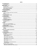
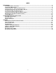
INDEX REPLACEMENT PARTS ....................................................................................................................................................... 4 ORDERING PARTS .............................................................................................................................................. 4 SAFETY INSTRUCTIONS .....................................................................................................................................................
INDEX MAINTENANCE .................................................................................................................................................................. 17 FILTER REPLACEMENT OR CLEANING .................................................................................................................... 17 CABINET FINISH MAINTENANCE ...........................................................................................................................
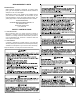
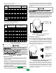
REPLACEMENT PARTS ORDERING PARTS When reporting shortages or damages, or ordering repair parts, give the complete unit model and serial numbers as stamped on the unit’s nameplate. Replacement parts for this appliance are available through your contractor or local distributor. For the location of your nearest distributor, consult the white business pages, the yellow page section of the local telephone book or contact: CONSUMER AFFAIRS GOODMAN MANUFACTURING COMPANY, L.P.
• • • CARBON MONOXIDE POISONING HAZARD Special Warning for Installation of Furnaces or Air Handling Units in Enclosed Areas such as Garages, Utility Rooms or Parking Areas Carbon monoxide producing devices (such as an automobile, space heater, gas water heater, etc.) should not be operated in enclosed areas such as unventilated garages, utility rooms or parking areas because of the danger of carbon monoxide (CO) poisoning resulting from the exhaust emissions.
GENERAL INFORMATION This unit is approved for outdoor installation ONLY. Rated performance is achieved after 72 hours of operation. Rated performance is delivered at the specified airflow. See outdoor unit specification sheet for split system models or product specification sheet for packaged and light commercial models. Specification sheets can be found at www.goodmanmfg.com for Goodman® brand products or www.amana-hac.com for Amana® brand products.
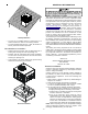
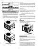
RIGGING DETAILS burners must not exceed the rated input shown on the rating plate. Overfiring of the unit could result in premature heat exchanger failure. HIGH ALTITUDE DERATE (U.S. INSTALLATIONS ONLY) IMPORTANT NOTE: The gas/electric units naturally derate with altitude. Do not attempt to increase the firing rate by changing orifices or increasing the manifold pressure. This can cause poor combustion and equipment failure. At all altitudes, the manifold pressure must be within 0.3 inches W.C.
There will be air in the gas supply line after testing for leaks on a new installation. Therefore, the air must be bled from the line by loosening the ground joint union until pure gas is expelled. Tighten union and wait for five minutes until all gas has been dissipated in the air. Be certain there is no open flame in the vicinity during air bleeding procedure. The unit is placed in operation by closing the main electrical disconnect switch for the unit. 8.
cooling. Units which will have economizers may use thermostats with two or three stages of cooling. All units can use single stage or multi-stage thermostats. Refer to figures later in this section for wiring. Sizing Between First and Second Stage Regulator Maximum Propane Capacities listed are based on 1 PSIG Pressure Drop at 10 PSIG Setting. Capacities in 1,000 BTU/HR NOMINAL PIPE SIZE, SCHEDULE 40 TUBING SIZE, O.D.
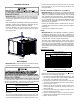
UNIT VOLTAGE The unit transformer is factory connected for 230V operation. If the unit is to operate on 208V, reconnect the transformer primary lead as shown on the unit wiring diagram. The induced draft blower on some models is equipped with a low speed 230V lead (blue) and a low speed 208V lead (black). If equipped, connect the induced draft blower low speed 208V lead (black) in place of the low speed 230V lead (blue). Place the unused 230V lead on the “PARK” terminal located on ignition control.
All ductwork exposed to the outdoors must include a weatherproof barrier and adequate insulation. A duct system should be installed in accordance with Standards of the National Board of Fire Underwriters for the Installation of Air Conditioning, Warm Air Heating and Ventilating Systems. Pamphlets No. 90A and 90B. The supply duct from the unit through a wall may be installed without clearance. However, minimum unit clearances as shown in the appendix must be maintained.
NORMAL SEQUENCES OF OPERATION FAN ONLY 1. Thermostat calls for FAN ONLY by energizing “G”. 2. The indoor blower is immediately energized at the low heat speed. 3. The indoor blower is immediately de-energized once thermostat call for FAN is removed. HEATING This unit is equipped with an ignition control that automatically lights the main burner. DO NOT attempt to light the main burners by any other method. 1. Thermostat calls for low or high stage heating. 2.
If the power to the unit is interrupted during the heating cycle, it may cause the secondary limit to trip. Once the blower compartment temperature drops below the limit reset temperature, the limit will automatically reset. Gas Supply And Manifold Check Gas supply pressure and manifold pressure with the burners operating must be as specified on the rating plate. Gas Inlet Pressure Check Gas inlet pressure must be checked and adjusted in accordance to the type of fuel being consumed.
Manifold Gas Pressure Gas Range Natural Propane Low Stage High Stage Low Stage High Stage 1.6 - 2.2" w.c. 3.2 - 3.8" w.c. 5.7 - 6.3" w.c. 9.7 - 10.3" w.c. With a properly designed system, the proper amount of temperature rise will normally be obtained when the unit is operated at rated input with the recommended blower speed. If the correct amount of temperature rise is not obtained, it may be necessary to change the blower speed. A higher blower speed will lower the temperature rise.
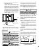
LOCOOL U6 HICOOL U7 LOHEAT U4 U3 K2 HIHEAT U5 P1 SPEEDUP K1 F1 SW1 FAULT BLOWER RECALL OFFDELAY STAGE DELAY ECON R C W1 W2 G Y1 Y2 Control Board (Top) NOTE: If necessary, adjust fan OFF delay settings to obtain satisfactory comfort level. space. It is the installing contractors responsibility to ensure the proper refrigerant sub-cooling at the condenser is adjusted for each application.
ABNORMAL OPERATION - HEATING OPEN THERMAL PROTECTION DEVICE If a limit switch opens, the gas valve is immediately deenergized, the induced draft and air circulating blowers are energized. The induced draft and air circulator blowers remain energized until the limit switch re-closes. The diagnostic LED (red) code for an open limit is four (4) flashes.
CONDENSER, EVAPORATOR, AND INDUCED DRAFT MOTORS NOTE: Some electronic thermostats also have a built-in compressor short cycle timer that may be longer than the three minute delay given above. If you are using an electronic thermostat and the compressor has not started after three minutes, wait an additional five minutes to allow the thermostat to complete its short cycle delay time. Bearings on the air circulating blower motor, condenser motor and the combustion fan motor are permanently lubricated.
MAIN BURNER FLAME (QUALIFIED SERVICER ONLY) Flames should be stable, soft and blue (dust may cause orange tips but must not be yellow). The flames must extend directly outward from the burner without curling, floating or lifting off. For further information on the yearly inspection, consult the User Manual. It is recommended that a qualified servicer inspect and service the unit at least once each year. Turn the unit on at the thermostat.
APPENDIX 19
IGNITION CONTROL DIAGNOSTIC INDICATOR CHART Red Light Signal Off 1 Flash 2 Flashes 3 Flashes 4 Flashes 5 Flashes 6 Flashes 7 Flashes 8 Flashes 9 Flashes Amber Light Signal Off On 1 Flash 2 Flashes Refer to Abnormal Heating or Cooling Operation Sections of this Manual Internal Control Failure External Lockout Pressure Switch Stuck Open Pressure Switch Stuck Closed Thermal Protection Device Open Flame Detected with Gas Valve Closed Short Cycle Compressor Delay (Cooling Only) Limit Opened Five (5) Times Withi
UNIT DIMENSIONS 47 51 FLUE EXHAUST HOOD 18 7/16 16 FLUE EXHAUST 1 3/8 C A 5 1/2 16 7 15/16 SUCTION/LIQUID PRESSURE PORTS BEHIND COMPRESSOR ACCESS PANEL B 2 3/4 COMBUSTION AIR INTAKE RETURN B HEAT EXCHANGE ACCESS PANEL 4 3/4 GAS SUPPLY ENTRANCE CONDENSATE DRAIN CONNECTION 3/4" NPT FEMALE SUPPLY 3 EVAPORATOR/CONTROL PANEL ACCESS PANEL 16 1/8 19 1/8 OF ER Y NT VIT E A C R G 7 5/16 7 7/8 20 24 DIMENSION (INCHES) MEDIUM LARGE A B 32 16 40 18 C 9 1/2 14 POWER WIRE ENTRANCE CONTROL W
*PG15*****41A* WIRING DIAGRAM HIGH VOLTAGE! DISCONNECT ALL POWER BEFORE SERVICING. MULTIPLE POWER SOURCES MAY BE PRESENT. FAILURE TO DO SO MAY CAUSE PROPERTY DAMAGE, PERSONAL INJURY OR DEATH.
*PG15*****41A* WIRING DIAGRAM HIGH VOLTAGE! DISCONNECT ALL POWER BEFORE SERVICING. MULTIPLE POWER SOURCES MAY BE PRESENT. FAILURE TO DO SO MAY CAUSE PROPERTY DAMAGE, PERSONAL INJURY OR DEATH.
*PG15*****41B* WIRING DIAGRAM HIGH VOLTAGE! DISCONNECT ALL POWER BEFORE SERVICING. MULTIPLE POWER SOURCES MAY BE PRESENT. FAILURE TO DO SO MAY CAUSE PROPERTY DAMAGE, PERSONAL INJURY OR DEATH. Wiring is subject to change. Always refer to the wiring diagram on the unit for the most up-to-date wiring.
*PG15*****41B* WIRING DIAGRAM HIGH VOLTAGE! DISCONNECT ALL POWER BEFORE SERVICING. MULTIPLE POWER SOURCES MAY BE PRESENT. FAILURE TO DO SO MAY CAUSE PROPERTY DAMAGE, PERSONAL INJURY OR DEATH. Wiring is subject to change. Always refer to the wiring diagram on the unit for the most up-to-date wiring.
MINIMUM CLEARANCES 48" MIN 12" MIN 3" MIN . 12" MIN 36" MIN (FOR SERVICE) NOTE: Roof overhang should be no more than 36". RECOMMENDED FILTER SIZES UNIT 2 Ton 2 1/2 Ton 3 Ton 3 1/2 -/ 4 Ton 5 Ton Min.
BLOWER PERFORMANCE DATA *PG152407041** - Rise Range: 35° - 65° F E.S.P 0.1 0.2 0.3 0.4 0.5 0.6 0.7 0.
PACKAGE UNITS - DUAL FUEL & GAS HOMEOWNER’S ROUTINE MAINTENANCE RECOMMENDATIONS We strongly recommend a bi-annual maintenance checkup be performed by a qualified service agency before the heating and cooling seasons begin. COMPRESSOR The compressor motor is hermetically sealed and does not require additional oiling. ANNUAL INSPECTION (QUALIFIED SERVICER ONLY) Your package unit should be inspected by a qualified installer, or service agency at least twice every year.