INSTALLATION & OPERATING INSTRUCTIONS for SPLIT SYSTEM CONDENSING UNITS All information contained herein is subject to change without notice. I0-101G Goodman Manufacturing Company, L.P. 2550 North Loop West, Suite 400, Houston, TX 77092 www.goodmanmfg.com © 2003-2004 Goodman Manufacturing Company, L.P.
INDEX company. Check the unit model number, specifications, electrical characteristics and accessories to determine if they are correct. In the event an incorrect unit is shipped, it must be returned to the supplier and must NOT be installed. The manufacturer assumes no responsibility for installation of incorrectly shipped units. Important Message to Homeowner ...................... 2 Codes and Regulations ....................................... 2 Inspection ..............................................
Close to the wall application assures free, unobstructed air to the other two sides. In more confined application spaces, such as corners, provide a minimum 10” clearance on all air inlet sides. Allow 18” minimum for service access to the compressor compartment and controls. This “close to the wall” application minimizes exposed tubing and wiring and reduces the space for children to run around the unit. This will help to avoid possible damage to the tubes or wiring and/or personal injury.
consideration is given the weather-tight integrity of the roof. The condensing unit contains moving components and can vibrate; therefore, sound is also a consideration in rooftop application. Since this unit discharges warm condenser air from the top with cooler air being drawn in three sides, plantings can be made in relatively close proximity to the unit. Owners should be advised to avoid lawn mower discharge toward the unit depositing debris on the fan coil surface reducing product efficiency.
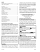
The recommended procedure for processing and charge adjustment is as follows: 1. Connect vacuum pump to both base valve service ports. 2. Evacuate tubing and evaporator through liquid and suction base valve ports, to 500 microns or less for a minimum of 30 minutes. Close valve to pump and wait 15 minutes. Vacuum should not rise above 800 microns. If unable to obtain 500 micorns, or vacuum rises above 800 microns over a 15 minute period, discontinue evacuation, pressurize and check for leaks.
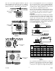
NOTE: System with over 50’ separation between condensing unit and evaporator may require oil charge adjustment. SPECIAL NOTE: Systems with MORE than 15’ of interconnecting tubing, please refer to Table 5 for line charge allowance per foot of tubing. LINE CHARGE ALLOWANCE (R-22) (oz./ft.) LINE O. D. (IN) LIQUID LINE 1/4 3/8 1/2 5/8 3/4 7/8 1 1/8 1 3/8 0.22 0.58 1.14 1.86 OIL CHARGE ADJUSTMENT SUCTION LINE UNIT MODEL (TONS) ADDITIONAL OIL CHARGE PER EACH ADDITIONAL 10' OF LINE (OZ.
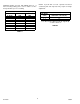
WIRING DIAGRAMS ALT.
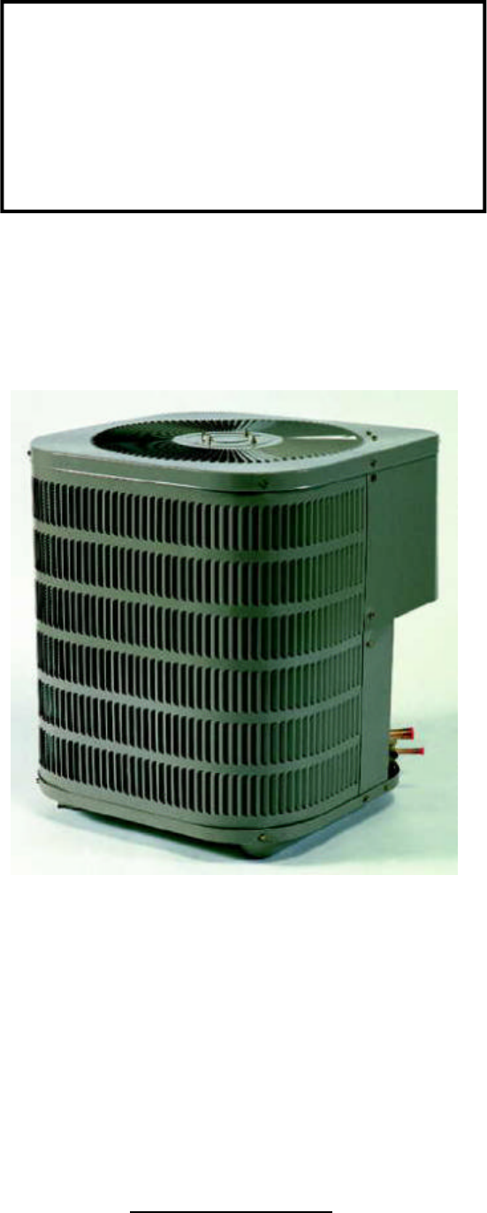
NOTE: SPECIFICATIONS AND PERFORMANCE DATA LISTED HEREIN ARE SUBJECT TO CHANGE WITHOUT NOTICE Quality Makes the Difference! All of our systems are designed and manufactured with the same high quality standards regardless of size or efficiency. We have designed these units to significantly reduce the most frequent causes of product failure. They are simple to service and forgiving to operate. We use quality materials and components. Finally, every unit is run tested before it leaves the factory.