TECHNICAL MANU AL MANUAL GME8 33-3/8" 80% Gas Furnace Upflow/Horizontal • Refer to current Service Manual RS6610004 for installation, operation, and troubleshooting information. • All safety information must be followed as provided in the Service Manual. • Refer to the appropriate Parts Catalog for part number information. • Model numbers listed on page 3. ® C This manual is to be used by qualified, professionally trained HVAC technicians only.
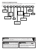
PRODUCT IDENTIFICATION The model and manufacturing number are used for positive identification of component parts used in manufacturing. Please use these numbers when requesting service or parts information.
PRODUCT IDENTIFICATION The model and manufacturing number are used for positive identification of component parts used in manufacturing. Please use these numbers when requesting service or parts information. GME80703BXC* GME80905CXC* GME81155CXC* All models are low NOx models. WARNING The United States Environmental Protection Agency (“EPA”) has issued various regulations regarding the introduction and disposal of refrigerants introduced into this unit.
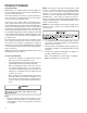
PRODUCT DESIGN General Operation GME8 furnaces are equipped with an electronic ignition device used to light the burners and an induced draft blower to exhaust combustion products. An interlock switch prevents furnace operation if the blower door is not in place. Keep the blower access door in place except for inspection and maintenance. This furnace is also equipped with a self-diagnosing electronic control module.
PRODUCT DESIGN Accessibility Clearances (Minimum) High Altitude Derate Unobstructed front clearanace of 24" for servicing is recommended. When this furnace is installed at high altitude, the appropriate High Altitude orifice kit must be installed. This is required due to the natural reduction in the density of both the gas fuel and combustion air as altitude increases. The kit will provide the proper design certified input rate within the specified altitude range.
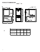
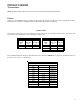
PRODUCT DIMENSIONS GME8*****XA UNITS A B C D GME80703BXC* 17.5 16 33-3/8 28 GME80905CXC* GME81155CXC* 21 19.5 33-3/8 28 All dimensions are in inches.
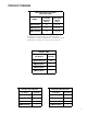
PRODUCT DESIGN PRESSURE SWITCH TRIP POINTS AND USAGE CHART * MODEL TRIP POINT ID BLOWER PRESSURE SWITCH ID BLOWER PRESSURE SWITCH PART # GME80703BXC* -0.70 B1370158 GME80905CXC* -0.75 B1370179 GME81155CXC* -1.40 B1370156 All installas above 7,000 ft. require a pressure switch change. For installations in Canada, the GME8 furnace is certified only to 4,500 ft. * Negative pressure readings are in inches of water column (*w.c.
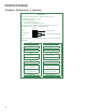
PRODUCT DESIGN Coil Matches: A large array of Amana® brand coils are available for use with the new GME8 furnaces, in either upflow or horizontal applications. These coils are available in both cased and uncased models (with the option of a field installed TXV expansion device). These 80% furnaces match up with the existing Amana® brand coils as shown in the chart below.
PRODUCT DESIGN Thermostats: NOTE: Complete lineup of thermostats can be found in the Thermostat Specification Sheets. Filters: Filters are required with this furnace and must be provided by the installer. The filters used must comply with UL900 or CAN/ULCS111 standards. Installing this furnace without filters will void the unit warranty. Upflow Filters This furnace has provisions for the installation of return air filters at the side and/or bottom return.
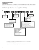
PRODUCT DESIGN Dual$aver Configuration & Operation Dual$aver This furnace is capable of the following heating modes: • Single Stage (Factory Setting) • Modified Two-Stage » Fixed 5-Min Low Stage » Auto Time (1-12 Min) Low Stage To change from the factory single-stage operation, adjust the dipswitches on the ignition control as follows: Off On Mode Mode Dipswitch 5 Min Fixed Auto 2nd Stage Delay Dipswitch Note: This furnace is designed to be used with a single-stage room thermostat.
FURNACE SPECIFICATIONS GME80703BXC* GME80905CXC* GME81155CXC* Input, Natural Gas (BTUH)(1) 70,000 90,000 115,000 Output, Natural Gas (BTUH)(1) 56,000 72,000 92,000 Output, LP (BTUH) 48,000 64,000 80,000 A.F.U.E. 80.0% 80.0% 80.0% .20 - .50 .20 - .50 .20 - .50 20 - 50 35 - 65 35 - 65 -0.60 -0.75 -1.40 10 X 8 10 X 10 10 X 10 1/2 1 1 MODEL Rated External Static (" w.c.) Temperature Rise (°F) Pressure Switch Trip Point ("w.c.
BLOWER PERFORMANCE SPECIFICATIONS BLOWER PERFORMANCE Model ( ) Heating Speed As Shipped GME8 0703BXC* GME8 0905CXC* GME8 1155CXC* Motor Speed (CFM & Temperature Rise vs. External Static Pressure) EXTERNAL STATIC PRESSURE (Inches Water Column) Tons AC at 0.5" ESP 0.1 0.2 0.3 0.4 0.5 0.6 0.7 0.8 CFM RISE CFM RISE CFM RISE CFM RISE CFM RISE CFM CFM CFM T1 2.5 875 59 793 65 736 70 674 77 592 88 556 509 460 T2 3.
TEMPERATURE RISE 10 20 30 40 30 50 60 70 80 90 100 40 50 60 700 600 CFM 90 100 2000 2200 2400 CFM 1800 1600 1400 OUTPUT BTU/HR x 1000 80 1200 1100 1000 900 70 800 FORMULAS 110 120 130 140 BTU OUTPUT = CFM x 1.08 x RISE BTU OUTPUT RISE = ÷ CFM 1.
WIRING DIAGRAMS GME8_CA HIGH VOLTAGE! DISCONNECT ALL POWER BEFORE SERVICING OR INSTALLING THIS UNIT. MULTIPLE POWER SOURCES MAY BE PRESENT. FAILURE TO DO SO MAY CAUSE PROPERTY DAMAGE, PERSONAL INJURY OR DEATH. WARNING:DISCONNECT POWER BEFORE SERVICING.WIRING TO UNIT MUST BE PROPERLY POLARIZED AND GROUNDED.
WIRING DIAGRAMS GME8_CB WARNING:DISCONNECTPOWERBEFORE SERVICING.WIRINGTOUNITMUST BE PROPERLYPOLARIZEDANDGROUNDED.
SCHEMATICS HIGH VOLTAGE! DISCONNECT ALL POWER BEFORE SERVICING OR INSTALLING THIS UNIT. MULTIPLE POWER SOURCES MAY BE PRESENT. FAILURE TO DO SO MAY CAUSE PROPERTY DAMAGE, PERSONAL INJURY OR DEATH. CIRCULATOR BLOWER HI COOL HEAT ELECTRONIC AIR CLEANER LO HEAT CIR PARK NEU EAC INDUCER EAC NEU IND R K2 K2 K3 RO2 RO1 K6 K3 ROLLOUT SWITCH TH K7 K1 XFMR HOT 24 VAC .