INSTALLATION INSTRUCTIONS FOR *(D, M)VC8 GAS FURNACE (CATEGORY I ) Installer: Affix all manuals adjacent to the unit. These furnaces comply with requirements embodied in the American National Standard / National Standard of Canada ANSI Z21.47·CSA2.3 Gas Fired Central Furnaces. ® C US RECOGNIZE THIS SYMBOL AS A SAFETY PRECAUTION. ATTENTION INSTALLING PERSONNEL As a professional installer, you have an obligation to know the product better than the customer.
Table of Contents SAFETY PRECAUTIONS ................................................................................................................................. 4 ADDITIONAL SAFETY CONSIDERATIONS ...................................................................................................... 5 SHIPPING INSPECTION ........................................................................................................................... 5 ELECTROSTATIC DISCHARGE (ESD) PRECAUTIONS .................
Table of Contents CIRCULATION AIR FILTERS ................................................................................................................... 23 HORIZONTAL INSTALLATIONS ................................................................................................................ 23 START-UP PROCEDURE AND ADJUSTMENT ....................................................................................................... 23 HEAT ANTICIPATOR SETTING ............................................
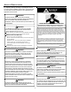
SAFETY PRECAUTIONS Adhere to the following warnings and cautions when installing, adjusting, altering, servicing, or operating the furnace. To ensure proper installation and operation, thoroughly read this manual for specifics pertaining to the installation and application of this product. WARNING TO PREVENT PERSONAL INJURY OR DEATH DUE TO IMPROPER INSTALLATION, ADJUSTMENT, ALTERATION, SERVICE OR MAINTENANCE, REFER TO THIS MANUAL .
PRODUCT APPLICATION This procedure is applicable to both installed and non-installed (ungrounded) furnaces. TO PREVENT PERSONAL INJURY OR DEATH DUE TO ASPHYXIATION, THIS 1. Disconnect all power to the furnace. Do not touch the FURNACE MUST BE CATEGORY I VENTED. DO NOT VENT USING integrated control module or any wire connected to the CATEGORY III VENTING. control prior to discharging your body’s electrostatic PROVISIONS MUST BE MADE FOR VENTING COMBUSTION PRODUCTS charge to ground.
LOCATION REQUIREMENTS AND CONSIDERATIONS home page. Next, click on the word “Product Registration” located on the left side of the Warranty page and complete the forms in the manner indicated on the Product Registration page. • • Product limited warranty certificates for models currently in production can be viewed at www.goodmanmfg.com or www.amanahac.com.
LOCATION REQUIREMENTS AND CONSIDERATIONS To ensure proper furnace operation, install, operate and maintain the furnace in accordance with these installation and operation instructions, all local building codes and ordinances. In their absence, follow the latest edition of the National Fuel Gas Code (NFPA 54/ANSI Z223.1), and/or CAN/CSA B149 Installation Codes, local plumbing or waste water codes, and other applicable codes.
LOCATION REQUIREMENTS AND CONSIDERATIONS hydrochloric acid cements and glues antistatic fabric softeners for clothes dryers and masonry acid washing materials • • • • • • • Vent Pipe Clearance to Combustibles6" using Single Wall Connector or 1" using B-1 vent. Top - 1" If the furnace is used in connection with a cooling unit, install the furnace upstream or in parallel with the cooling unit coil. Premature heat exchanger failure will result if the cooling unit coil is placed ahead of the furnace.
COMBUSTION & VENTILATION CATEGORY I VENTING AIR REQUIREMENTS g. If improper venting is observed during any of the above tests, the common venting system must be corrected. Corrections must be in accordance with the latest edition of the National Fuel Gas Code NFPA 54/ANSI Z223.1 and/or CAN/ CSA B149 Installation Codes. If resizing is required on any portion of the venting system, use the appropriate table in Appendix G in the latest edition of the National Fuel Gas Code ANSI Z223.
EXTERIOR MASONRY CHIMNEYS - CATEGORY I FURNACES ONLY heating/cooling costs but have created a problem supplying combustion and ventilation air for gas fired and other fuel burning appliances. Appliances that pull air out of the house (clothes dryers, exhaust fans, fireplaces, etc.) increase the problem by starving appliances for air.
EXTERIOR MASONRY CHIMNEYS - CATEGORY I FURNACES ONLY 11. Reconnect the induced draft blower power leads. NOTE: If the wires are not long enough, pull extra wire from the wire bundle in the blower compartment. 12. Reconnect the flue pipe, and the pressure switch tubing. Ensure that all wires and the pressure switch tubing is at least one inch from the flue pipe, or any other hot surface. 13. Restore power to furnace.
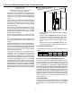
EXTERIOR MASONRY CHIMNEYS - CATEGORY I FURNACES ONLY If the chimney does not meet these termination requirements, but all other requirements in the checklist can be met, it may be possible for a mason to extend the chimney. If this will not be practical, see Fix 1. Proper Chimney Termination? (Check 1) 10' or Less 2' Min. Chimney channel free of solid and liquid fuel appliances? (Check 2) Change venting arrangements (Fix 2) 2' Min. 3' Min.
EXTERIOR MASONRY CHIMNEYS - CATEGORY I FURNACES ONLY Liquid fuel appliances include oil furnaces, oil-fired boilers and Next, use a flashlight and small mirror to sight up the liner. B vent must be supported so as to not come into direct contact oil-fired water heaters. with the chimney walls or tile liner. If it is not, it can probably be Appliances which burn propane (sometimes referred to as LP rehung so as to be acceptable.
ELECTRICAL CONNECTIONS Gas Code NFPA 54/ANSI Z223.1 - latest edition and in the National Standard of Canada, CAN/CSA B149.1 and CAN/CSA B149.2 - latest editions and amendments, then the clay tile liner can probably be used as a vent for the gas appliances.
ELECTRICAL CONNECTIONS and in the National Standard of Canada, CAN/CSA B149.1 and CAN/CSA B149.2 - latest editions and amendments. WARNING HIGH VOLTAGE ! To install the liner, read and follow the liner manufacturer’s instructions and your local codes. Excess liner length should be pulled out of the chimney and cut off. Use caution when doing this, as the cut edges of flexible liners may be sharp. Do not spiral excess liner inside of the chimney. Support the liner as recommended by the liner manufacturer.
ELECTRICAL CONNECTIONS To ensure proper unit grounding, the ground wire should run from the furnace ground screw located inside the furnace junction box all the way back to the electrical panel. NOTE: Do WARNING not use gas piping as an electrical ground. To confirm proper EDGES OF SHEET METAL HOLES MAY BE SHARP. USE GLOVES AS A unit grounding, turn off the electrical power and perform the PRECAUTION WHEN REMOVING HOLE PLUGS. following check. 1.
ELECTRICAL CONNECTIONS DIP switch to the desired ON/OFF position. Turn power back on. Refer to the following figure.
GAS SUPPLY AND PIPING A heat pump thermostat with three stages of heat is required to to all local codes, and have a minimum temperature rating of properly use a two-stage furnace in conjunction with a heat 105°C. All line voltage wire splices must be made inside the pump. Refer to the fossil fuel kit installation instructions for furnace junction box. additional thermostat requirements.
CIRCULATING AIR air temperature rise must be within the range listed on the furnace nameplate. Should this appliance be converted to LP, refer to the instructions included in the factory authorized LP conversion kit. AND FILTERS GAS PIPING CONNECTIONS WARNING TO AVOID POSSIBLE UNSATISFACTORY OPERATION OF EQUIPMENT DAMAGE DUE TO UNDERFIRING OR EQUIPMENT, USE THE PROPER SIZE OF NATURAL /PROPANE GAS PIPING NEEDED WHEN RUNNING PIPE FROM THE METER/TANK TO THE FURNACE.
GAS SUPPLY • • • AND PIPING Install a manual shutoff valve between the gas meter and unit within six feet of the unit. If a union is installed, the union must be downstream of the manual shutoff valve, between the shutoff valve and the furnace. Tighten all joints securely. Connect the furnace to the building piping by one of the following methods: – – Rigid metallic pipe and fittings. – Use listed gas appliance connectors in accordance with their instructions.
CIRCULATING AIR PROPANE GAS TANKS AND PIPING 5 to 15 PSIG (20 PSIG Max.) First Stage Regulator WARNING IF THE GAS FURNACE IS INSTALLED IN A BASEMENT, AN EXCAVATED AREA OR CONFINED SPACE , IT IS STRONGLY RECOMMENDED TO AND 200 PSIG Maximum FILTERS Continuous 11" W.C. Second Stage Regulator CONTACT A PROPANE SUPPLIER TO INSTALL A GAS DETECTING WARNING DEVICE IN CASE OF A GAS LEAK. • SINCE PROPANE GAS IS HEAVIER THAN AIR, ANY LEAKING GAS CAN SETTLE IN ANY LOW AREAS OR CONFINED SPACES.
START-UP PROCEDURE AND ADJUSTMENT A closed return duct system must be used, with the return duct connected to the furnace. NOTE: Ductwork must never be attached to the back of the furnace. For installations requiring more than 1800 CFM, use a bottom return or two sided return. Supply and return connections to the furnace may be made with flexible joints to reduce noise transmission.
START-UP PROCEDURE AND ADJUSTMENT ply with UL900 or CAN/ULCS111 standards. If the furnace is approved method. Verify that all required kits (propane gas, high altitude, etc.) have been appropriately installed. installed without filters, the warranty will be voided. NOTE: An undersized opening will cause reduced airflow. The FURNACE STARTUP 1. Close the manual gas shutoff valve external to the furnace. bottom return is set up as a knock out. 2. Turn off the electrical power to the furnace.
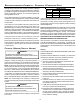
START-UP PROCEDURE AND ADJUSTMENT Manometer Hose Open to Atmosphere INLET OUTLET Common Terminal(C) High Fire Coil Terminal (HI) Low Fire Coil Terminal (LO) i Gas Valve On/Off Selector Switch Inlet Pressure Tap 1/8 NPT White-Rodgers Model 36G54 (Two-Stage) Open to Atmosphere Manometer Hose Outlet Pressure Boss Manometer High Fire Regulator Adjust Regulator Vent Outlet Pressure Tap 1/8 NPT Honeywell Model VR9205 Connected to Manometer 1.
START-UP PROCEDURE AND ADJUSTMENT 9. Close thermostat “R” and “W2” contacts to provide a call for high stage heat. 10. Remove regulator cover screw from the high (HI) outlet pressure regulator adjust tower and turn screw clockwise to increase pressure or counterclockwise to decrease pressure. Replace regulator cover screw. 11. Turn off all electrical power and gas supply to the system. 12. Remove the manometer hose from the hose barb fitting or outlet pressure boss. 13. Replace outlet pressure tap: a.
START-UP PROCEDURE AND ADJUSTMENT 4. Calculate the furnace input in BTUs per hour (BTU/hr). Input equals the sum of the installation’s gas heating value and a conversion factor (hours to seconds) divided by the number of seconds per cubic foot. The measured input must not be greater than the input indicated on the unit rating plate.
START-UP PROCEDURE AND ADJUSTMENT The cooling system manufacturer’s instructions must be checked for required air flow. Any electronic air cleaners or other devices may require specific air flows, consult installation instructions of those devices for requirements. 3. Knowing the furnace model, locate the high stage cooling air flow charts in the Specification Sheet applicable to your model. Look up the cooling air flow determined in step 2 and find the required cooling speed and adjustment setting.
START-UP PROCEDURE AND ADJUSTMENT 7. Select the heating speed for your model from the heating speed chart in the Specification Sheet. The adjust setting (already established by the cooling speed selection) determines which set of speeds are available. The selected speed must provide a temperature rise within the rise range listed with the particular model. Example: The *MVC80704BX is set for 990 CFM on cooling, the “ADJUST” is set to “+” (plus).
COMFORTNET™ SYSTEM COMFORTNET™ SYSTEM ECM motor. If the outdoor unit or thermostat is responsible for determining the demand, it calculates the demand and OVERVIEW transmits the demand along with a fan request to the indoor unit. The indoor unit then sends the demand to the ECM The ComfortNet system (or CT system) is a system that inmotor. The table below lists the various ComfortNet syscludes a ComfortNet compatible furnace and air conditioner or tems, the operating mode, and airflow demand source.
COMFORTNET™ SYSTEM FOSSIL FUEL APPLICATIONS This furnace can be used in conjunction with a ComfortNet™ compatible heat pump in a fossil fuel application. A fossil fuel application refers to a combined gas furnace and heat pump installation which uses an outdoor temperature sensor to determine the most cost efficient means of heating (heat pump or gas furnace). When used with the CTK01AA thermostat, the furnace/heat pump system is automically configured as a fossil fuel system.
COMFORTNET™ SYSTEM ACCESSING AND NAVIGATING THE ADVANCED FEATURES MENUS the change is not accepted, the display will show “FAIL” then revert to the Fault Screen. The advanced system features are accessed using the ComfortNet thermostat. These advanced features are accessed as follows: • On the CT thermostat Home Screen Display, touch the Menu key to display additional key choices. • Touch and hold the Installer Config key for approximately 3 seconds to enter the Thermostat Options Configuration menu.
COMFORTNET™ SYSTEM FURNACE ADVANCED FEATURES MENUS CONFIGURATION Submenu Item Number of Heat Stages (HT STG) Indication (for Display Only; not User Modifiable) Displays the number of furnace heating stages Input Rate (BTU/HR) Motor HP (1/2, ¾, or 1 MTR HP) Displays the furnace input rate in kBtu/hr Displays the furnace indoor blower motor horsepower DIAGNOSTICS Submenu Item Indication/User Modifiable Options Comments Fault 1 (FAULT #1) Most recent furnace fault For dis play only Fault 2 (FAULT #2
COMFORTNET™ SYSTEM NON-COMM (APPLIES ONLY TO A CT COMPATIBLE FURNACE MATCHED WITH A NON-CT COMPATIBLE SINGLE STAGE AIR CONDITIONER) Submenu Item User Modifiable Options Comments Cool Airflow (CL CFM) 18, 24, 30, 36, 42, 48, or 60, default is 18 Selects the airflow for the non-CT compatible single stage AC unit Cool Airflow Trim (CL TRM) -10% to +10% in 2% increments, default is 0% A, B, C, or D, default is A Cool ON Delay (CL ON) 5, 10, 20, or 30 seconds, default is 5 seconds Selects the airflow t
OPERATIONAL CHECKS & SAFETY CIRCUIT DESCRIPTION LED LED Status Off 1 Flash Indication Possible Causes Corrective Action(s) Notes & Cautions x None x Depress once quickly for a powerup reset x Depress and hold for 2 seconds for an out-of-box reset x None x Normal condition x Communications Failure x None x Communications Failure x None x Depress Learn Button x Verify that bus BIAS and TERM dipswitches are in the ON position.
OPERATIONAL CHECKS & SAFETY CIRCUIT DESCRIPTION • Gas valve opens at end of igniter warm up period, delivering gas to burners and establishing flame. • Integrated control module monitors flame presence. Gas • valve will remain open only if flame is detected. If the thermostat call is for low heat, gas valve and induced draft blower will continue on low stage. If the call is for high heat, the gas valve and induced draft blower will change to high stage.
TROUBLESHOOTING & MAINTENANCE FLAME SENSOR The flame sensor is a probe mounted to the burner/manifold assembly which uses the principle of flame rectification to determine the presence or absence of flame. TROUBLESHOOTING ELECTROSTATIC DISCHARGE (ESD) PRECAUTIONS NOTE: Discharge body’s static electricity before touching unit. An electrostatic discharge can adversely affect electrical components.
MISCELLANEOUS FAULT RECALL • The ignition control is equipped with a momentary push-button switch that can be used to display the last six faults on the dual 7-segment LED’s. The control must be in Standby Mode (no thermostat inputs) to use the feature. Depress the switch for approximately 2 seconds. Release the switch when the LED’s are turned off. The last six faults will be displayed most recent to least recent on the dual 7-segment LED’s.
MISCELLANEOUS BURNERS Visually inspect the burner flames periodically during the heating season. Turn on the furnace at the thermostat and allow several minutes for flames to stabilize, since any dislodged dust will alter the flames normal appearance. Flames should be stable, quiet, soft, and blue (dust may cause orange tips but they must not be yellow). They should extend directly outward from the burners without curling, floating, or lifting off.
x Furnace fails to operate. x Integrated control module LED display provides E1 error code. x ComfortNet™ thermostat “Call for Service” icon illuminated. x ComfortNet™ thermostat scrolls “Check Furnace” message. x Induced draft blower runs continuously with no further furnace operation. x Integrated control module LED display provides E2 error code. x ComfortNet™ thermostat “Call for Service” icon illuminated. x ComfortNet™ thermostat scrolls “Check Furnace” message.
x Furnace fails to operate. x Integrated control module LED display provides E7 error code. x ComfortNet™ thermostat “Call for Service” icon illuminated. x ComfortNet™ thermostat scrolls “Check Furnace” message. E7 x Problem with igniter circuit. x Flame sense micro amp signal is low E6 E7 WEAK FLAME IGNITER FAULT Not Displayed Not Displayed x Open Fuse E5 E6 E4 IMPROPER FLAME x Flame sensed with no call for heat.
E8 E9 EA d0 x Furnace fails to operate on high stage; furnace operates normally on low stage. x Integrated control module LED display provides E9 error code. x Furnace fails to operate. x Integrated control module LED display provides EA error code. x ComfortNet™ thermostat “Call for Service” icon illuminated. x ComfortNet™ thermostat scrolls “Check Furnace” message. x Furnace fails to operate. x Integrated control module LED display provides d0 error code.
b3 x Furnace operates at reduced performance. x Airflow delivered is less than expected. x Integrated control module LED display provides b3 error code. b1 x Furnace fails to operate. x Integrated control module LED display provides b1 error code. x ComfortNet™ thermostat “Call for Service” icon illuminated. x ComfortNet™ thermostat scrolls “Check Furnace” message. b2 b0 x Furnace fails to operate. x Integrated control module LED display provides b0 error code.
x Airflow is lower than demanded. b9 b9 b7 MOTOR PARAMS x Circulator blower motor does not have enough information to operate properly. x Motor fails to start 40 consecutive times. b7 LOW ID AIRFLOW b6 MOTOR VOLTS x Circulator blower motor shuts down for over or under voltage condition. x Circulator blower motor shuts down due to over temperature condition on power module. b6 x Furnace fails to operate. x Integrated control module LED display provides b7 error code.
STATUS CODES INTERNAL CONTROL FAULT/NO POWER O E E E E E E E E P 0 1 2 3 4 5 6 7 NORMAL OPERATION E E E d d b b b b b b b 8 9 A 0 4 0 1 2 3 4 5 6 HIGH STAGE PRESSURE SWITCH STUCK CLOSED AT START OF HEATING CYCLE b b C C 7 9 1 2 INCOMPLETE PARAMETERS SENT TO MOTOR LOCKOUT DUE TO EXCESSIVE RETRIES LOW STAGE PRESSURE SWITCH STUCK CLOSED AT START OF HEATING CYCLE LOW STAGE PRESSURE SWITCH STUCK OPEN OPEN HIGH LIMIT SWITCH FLAME DETECTED WHEN NO FLAME SHOULD BE PRESENT OPEN FUSE LOW FLAME SIGNAL IGNITE
AIR FLOW DATA Speed Selection Dip Switches Cool Selection Switches Adjust Selection Switches Profile Selection Switches Model Heat Selection Switches *DVC80703BX* TAP 1 2 3 4 5 6 7 8 A OFF OFF OFF OFF OFF OFF OFF OFF OFF B ON ON OFF ON OFF ON OFF C OFF ON OFF ON OFF ON OFF ON D ON ON ON ON ON ON ON Profiles ON Tap Pre-Run Short-Run OFF Delay A ------- -------- 60 sec/100% B ------- 30 sec/50% 60 sec/100% C ------- 7.
*MVC8_AA WIRING DIAGRAM TO 115 VAC/ 1 POWER SUPPLY W ITH JUNCTION BOX 24V HUM.
*MVC8_AB, *DVC8_AA WIRING DIAGRAM TO 115 VAC/ 1 Ø /60 HZ POWER SUPPLY WITH OVERCURRENT PROTECTION DEVICE GND JUNCTION BOX ID BLOWER TWO-STAGE PRESSURE SWITCH ASSEMBLY 24V HUM.
Goodman Manufacturing Company, L.P. 5151 San Felipe, Suite 500, Houston, TX 77056 www.goodmanmfg.com © 2009-2010 Goodman Manufacturing Company, L.P.