
ACNF Installation Manual


12
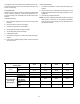
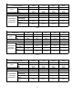
Pipe
Gauge
Tightening
Torque
Flare
Shape
1/4"
(Ø 6.4)
10.5~12.7 ft/lbs
(124.9~152.7 lb/in)
14.2~17.2 N.m
(144~176 kgf.cm)
5/16"
8.3
11/32"
8.7
3/8"
Ø9.5
24.1~29.4 ft/lbs
(289.0~353.2 lb/in)
32.7~39.9 N.m
(333~407 kgf.cm)
15/32"
'12.0
1/2"
12.4
1/2"
Ø12.7
36.5~44.6 ft/lbs
(437.4~534.6 lb/in)
49.5~60.3 N.m
(504~616 kgf.cm)
19/32"
15.4
5/8"
15.8
5/8"
Ø15.9
45.6~556.0 ft/lbs
(546.8~668.3 lb/in)
61.8~75.4 N.m
(630~770 kgf.cm)
23/32"
18.6
3/4"
'19.0
3/4"
Ø19.1
71.7~87.5 ft/lbs
(859.2~1050 lb/in)
97.2~118.6 N.m
(990~1210 kgf.cm)
29/32"
22.9
29/32"
23.3
Flare
Dimension A
Min Max
A
90° 4+
4
5
°
2
+
R0.4~0.8
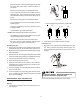
Leak Testing (Nitrogen or Nitrogen-Traced)
Pressure test the system, using dry nitrogen and soapy water
to locate any leaks in the system. If you wish to use a leak
detector, charge the system to 10 psi using the appropriate
refrigerant, then use nitrogen to finish charging the system
to working pressure. Apply the detector to suspect areas. If
leaks are found, repair them. After repair, repeat the pres-
sure test. If no leaks exist, proceed to System Evacuation.
Insulation
Cover all exposed parts of the flare pipe joints and refrigerant
pipe on both the liquid and gas sides, with insulating materi-
als. Incomplete coverage may cause water condensation.
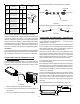
CONNECTING THE AIR HANDLER TO THE
OUTDOOR UNIT
To receive optimum throttle efficiency, mount the orifice as
level horizontally as possible. Anti-shock rubber should be
wrapped on the external parts of the orifice to reduce noise.
Gas side
Liquid side
Orifice
Figure 22
1. Mark the data plate with the orifice installed.
2. Purchase the fittings according to the requirements in
the manuals.
3. Refer to the diagrams for reference while installing.
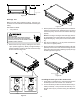
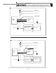
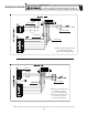
COOLING & HEATING: Correct installation, Figure 23.
Liquid side
Liquid side
OUTDOOR
INDOOR
Figure 23
COOLING & HEATING: Do not install as shown in Figure 24.
OUTDOOR
INDOOR
OUTDOOR
INDOOR
Liquid side
Liquid side
Figure 24
CONNECTING THE DRAIN PIPE - INDOOR UNIT
Purchased from your dealer, polyethylene tubing can be used
as the drain pipe (outside diameter 1” - 1/10” (29-31mm);
(inside diameter 1” or 25mm).
To prevent water from ingressing into the air conditioner when
the air conditioner is not operating, the drain pipe should be
slanted down toward the outdoor (outlet side) at a degree of
over 1/50. Avoid any bulges or water deposits.
Take care not to put undue stress on the drain pipe when
connecting to prevent its pulling away from the body. One
support point should be set every 39” - 59” (1-1.5m) to help
support the drain pipe and prevent it from pulling. The drain
pipe can also be tied to the connecting pipe for support.
If the drain pipe is long, tighten the indoor part with a sealant
to prevent its loosening.
If the drain pipe’s outlet is higher than the body’s pump joint,
arrange the pipe as vertically as possible, with the left dis-
tance less than 8” (200mm). Otherwise, the water will over-
flow when the air conditioner ceases operation. Only avail-
able with units with plugs.
The end of the drain pipe should be over 2” (50mm) higher
than the ground or the bottom of the drainage chute. Do not
immerse it in water. If water is discharge directly into sew-
age, make a U-form aqua seal by bending the pipe up to
prevent odorous gases from entering the home through the
drain pipe.
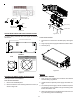
Drain Pipe Installation for the unit with pump: Figure 25.
Lean over 1/50
<8.0”
(200mm)
39” - 59” (1-1.5m)
Figure 25