® C IO-286B US INSTALLATION & OPERATING INSTRUCTIONS FOR ARUF, ARPF, ADPF, AEPF SERIES AIR HANDLER Made in the USA by: Goodman Manufacturing Company, L.P. 2550 North Loop West, Suite 400 - Houston, Texas 77092 www.goodmanmfg.com or www.amana-hac.com © 2004-2006 Goodman Manufacturing Company, L.P.
INDEX IMPORTANT SAFETY INSTRUCTIONS Recognize Safety Symbols, Words, and Labels The following symbols and labels are used throughout this manual to indicate immediate or potential hazards. It is the owner’s responsibility to read and comply with all safety information and instructions accompanying these symbols. Failure to heed safety information increases the risk of serious personal injury or death, property damage and/or product damage. INTRODUCTION .....................................................
WARNING WARNING THIS PRODUCT IS FACTORY SHIPPED FOR USE WITH A 208-240/1/60 ELECTRICAL POWER SUPPLY. THIS AIR HANDLER MUST NOT BE RECONFIGURED TO OPERATE WITH ANY OTHER POWER SUPPLY. ONLY INDIVIDUALS MEETING THE REQUIREMENTS OF AN “ENTRY LEVEL TECHNICIAN” AS SPECIFIED BY THE AIR CONDITIONING AND REFRIGERATION INSTITUTE (ARI) MAY USE THIS INFOMRATION. ATTEMPTIMG TO INSTALL OR REPAIR THIS UNIT WITHOUT SUCH BACKGROUND MAY RESULT IN PRODUCT DAMAGE, PERSONAL INJURY, OR DEATH.
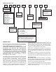
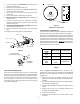
MODEL IDENTIFICATION A R U F 3642 1 6 A A Product Type: A: Single Piece Air Handler Minor Revision: Application: C: Ceiling Mount PSC Motor D: Downflow PSC Motor E: Multi-Position Variable Speed Motor R: Multi-Position PSC Motor W:Wall Mount PSC Motor A: Minor Revision R-22 Only Expansion Device: Not used for inventory management Electrical: F: Flowrater 1: 208/240V 1 Phase 60 Hz Major Revision: A: R-22 Only Refrigerant: R:22 only: No numeric character 6: R-22 or R-410A Cabinet Finish:
If an incorrect unit is supplied, it must not be installed and it is to be returned to the supplier. The manufacturer assumes no responsibility for the installation of incorrectly delivered units. CFM 600 800 1000 1200 1400 1600 1800 2000 The evaporator coil contains a high-pressure inert gas holding charge. ELECTRIC HEAT WARNING REFER TO THE “INSTALLING ELECTRIC HEAT” SECTION OF THIS MANUAL AND THE INSTRUCTIONS PROVIDED WITH THE HEAT KIT FOR THE CORRECT INSTALLATION PROCEDURE.
sturdy, non-porous material. In installations that may lead to physical damage (i.e. a garage) it is advised to install a protective barrier to prevent such damage. WARNING HIGH VOLTAGE!! DISCONNECT ALL POWER BEFORE INSTALLING OR SERVICING THIS UNIT. MULTIPLE POWER SOURCES MAY BE PRESENT. FAILURE TO DO SO MAY CAUSE PROPERTY DAMAGE, PERSONAL INJURY, OR DEATH. DUCTWORK This air handler is designed for a complete supply and return ductwork system.
Low Voltage Connections Several combinations of low voltage schemes are available, depending on the presence of a heat kit and whether the heat kit is single-stage or multi-staging. The low voltage connections are determined by whether the outdoor unit is a condenser or heat pump. The 24V-control voltage connects the air handler to the room thermostat and condenser. Low voltage wiring is to be copper conductors.
1. Loosen the 13/16 nut 1 TURN ONLY. No pressure loss indicates possible leak. 2. Remove the nut and discard the cap. 3. Remove the check piston to verify it is correct. See piston kit chart in instructions. 4. Use a tube cutter to remove the spin closure on the suction line. 5. Remove the tailpiece clamped to the exterior. 6. Slide the 13/16 nut into position. Braze tailpiece to the liquid tube. 7.
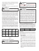
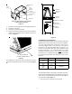
Return Air Side of Unit Access Panel Rear Channel Bracket WRAPPER Zee Coil Support Bracket INSULATION JACKET Coil Retaining Bracket ZEE COIL SUPPORT Tie Bracket WRAPPER STIFFENER NOTE: The filter provision is not applicable in THIS downflow application. DRAIN PAN INSULATION KIT Figure 4 7. 8. 9. 10. BLOWER ASSEMBLY Install the zee coil supports and the wrapper stiffeners. Install the tie bracket. Install the rear channel bracket.
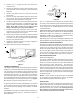
2. Remove the “J” shaped bracket that retains the evaporator coil. Drain Connection 3. Remove the flowrater from the lower left side access panel and slide out the evaporator coil and horizontal drain pan. Air Handler 4. Remove the gasket from the horizontal pan drain connections. 5. Remove the oval shaped plastic plug from the left side access panel. Remove the oval shaped rubber gasket seal from the lower right side access panel. 2" MIN. POSITIVE LIQUID SEAL REQUIRED AT TRAP 3" MIN. Figure 8 6.
The AEPF product uses a General Electric ECMTM motor. This motor provides many features not available on the traditional PSC motor.
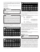
Thermostat Wiring Use thermostat wiring diagram Figures 9 thru 12 and those provided with the thermostat when making these connections. NOTE: DO NOT USE THESE DIAGRAMS FOR AEPF MODELS. SEE SUPPLEMENTAL INSTALLATION AND OPERATING INSTRUCTIONS FOR AEPF MODELS. ! WARNING TO AVOID POSSIBLE ELECTRICAL SHOCK, PERSONAL INJURY, OR DEATH, DISCONNECT THE POWER BEFORE SERVICING. ROOM THERMOSTAT W Y G #18 GA.
! WARNING TO AVOID POSSIBLE ELECTRICAL SHOCK, PERSONAL INJURY, OR DEATH, DISCONNECT THE POWER BEFORE SERVICING. FIGURE 11 ARUF/ARPF/ADPF 18-60 10 KW & BELOW TYPICAL H/P ROOM THERMOSTAT HEAT PUMP C B L U E W2 W H I T E O Y R O R A N G E Y E L L O W Y O C W2 #18 GA. 7 WIRE AR UNIT G R E R E D R Y O SEE NOTE #3 W BL R R RED G G GREEN BR W W WHITE BL BL BLUE #18 GA. 5 WIRE (OPTIONAL) OUTDOOR THERMOSTAT CLOSE ON TEMPERATURE FALL #18 GA.
THERMOSTATS Note: Second Stage heat can be accomplished by multistage heating thermostat or the addition of an outdoor thermostat as shown in Figures 12 and 13. • • • Goodman part number CHT18-60 is a single-stage cool and single-stage heat thermostat. • Goodman part number HPT18-60 is a single-stage cool, twostage heat pump thermostat. The first stage is heat pump heating and the second stage is optional electric heat.