
Install Instructions


6
WARNING
HIGH VOLTAGE!!
DISCONNECT ALL POWER BEFORE INSTALLING OR
SERVICING THIS UNIT. MULTIPLE POWER SOURCES
MAY BE PRESENT. FAILURE TO DO SO MAY CAUSE
PROPERTY DAMAGE, PERSONAL INJURY, OR DEATH.
WARNING
THE UNIT MUST HAVE AN UNINTERRUPTED,
UNBROKEN ELECTRICAL GROUND TO MINIMIZE THE
POSSIBILITY OF PERSONAL INJURY IF AN ELECTRICAL
FAULT SHOULD OCCUR. THE ELECTRICAL GROUND
CIRCUIT MAY CONSIST OF AN APPROPRIATELY SIZED
ELECTRICAL WIRE CONNECTING THE GROUND LUG
IN THE UNIT AND CONTROL BOX WIRE TO THE
BUILDING’S ELECTRICAL SERVICE PANEL. OTHER
METHODS OF GROUNDING ARE PERMITTED IF
PERFORMED IN ACCORDANCE WITH THE “NATIONAL
ELECTRIC CODE” (NEC)/”AMERICAN NATIONAL
STANDARDS INSTITUTE” (ANSI)/”NATIONAL FIRE
PROTECTION ASSOCIATION” (NFPA) 70 AND LOCAL/
STATE CODES. IN CANADA, ELECTRICAL GROUNDING
IS TO BE IN ACCORDANCE WITH THE CANADIAN
ELECTRIC CODE CSA C22.1. FAILURE TO OBSERVE
THIS WARNING CAN RESULT IN ELECTRICAL SHOCK
THAT CAN CAUSE PERSONAL INJURY OR DEATH.
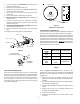
Inspection of the Building Electrical Service
This unit is designed for single-phase electrical supply. DO
NOT OPERATE ON A THREE-PHASE POWER SUPPLY.
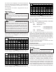
Measure the power supply to the unit. The supply voltage
must be in agreement with the unit nameplate power
requirements and within the range shown in Table 6.
Nominal Input Minimum Voltage Maximum Voltage
208/240 187 253
Table 6
Wire Sizing
Wire size is important to the operation of your equipment.
Use the following check list when selecting the appropriate
wire size for your unit.
• Wire size must carry the Minimum Circuit
Ampacity (MCA).
Refer to the NEC (USA) or CSA (Canada) for wire sizing.
The unit MCA for the air handler and the optional electric
heat kit can be found on the unit Series and Rating
Plate.
• Wire size allows for no more than a 2% voltage
drop from the building breaker/fuse panel to the
unit.
Refer to the latest edition of the National Electric Code
or in Canada the Canadian Electric Code when
determining the correct wire size. The following table
shows the current carrying capabilities for copper
conductors rated at 75
o
C with a 2% voltage drop. Use
Table 7 to determine the voltage drop per foot of various
conductors.
sturdy, non-porous material. In installations that may lead
to physical damage (i.e. a garage) it is advised to install a
protective barrier to prevent such damage.
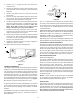
DUCTWORK
This air handler is designed for a complete supply and return
ductwork system.
CAUTION
DO NOT OPERATE THIS PRODUCT WITHOUT ALL
DUCTWORK ATTACHED.
To ensure correct system performance, the ductwork is to
be sized to accommodate 375-425 CFM per ton of cooling
with the static pressure not to exceed .5" WC. Inadequate
ductwork that restricts airflow can result in improper
performance and compressor or heater failure. Ductwork
is to be constructed in a manner that limits restrictions
and maintains suitable air velocity. Ductwork is to be sealed
to the unit in a manner that will prevent leakage.
Return Ductwork. DO NOT TERMINATE THE RETURN
DUCTWORK IN AN AREA THAT CAN INTRODUCE TOXIC,
OR OBJECTIONABLE FUMES/ODORS INTO THE
DUCTWORK. The return ductwork is to be introduced into
the air handler bottom (upflow configuration).
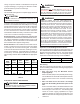
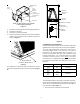
Return Air Filters. Each installation must include a return
air filter. This filtering may be performed at the air handler
or externally such as a return air filter grille. Air handlers
mounted in the downflow orientation, including “B” series,
require external filtering. A washable filter is available as
an accessory. To ensure optimum performance frequent
filter cleaning is advised. Refer to Table 5 for the appropriate
filter.
ARUFor
ARPF
model
ADPF
model
AEPF
model
Filter
Number
Qty
Required
1729
1824
3030 3030 1830 FIL-36-42 1
1931
3642 3042 3036
3743 FIL 48-61 1
4860 4860 4260
1824 N/A FIL 18-32 1
Table 5
ELECTRICAL SUPPLY WIRE AND MOP
WARNING
TO AVOID THE RISK OF FIRE OR EQUIPMENT DAMAGE,
USE ONLY COPPER CONDUCTORS.