
Install Instructions


7
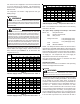
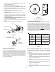
10 15 20 25 30 35 40 45
14 75 50 37 NR NR NR NR NR
12 118795947NRNRNRNR
10 188 125 95 75 63 54 NR NR
8 301 201 150 120 100 86 75 68
6 471 314 235 188 157 134 118 110
*Based on NEC 1996
Maximum Allowable Length in Feet
to Limit Voltage Drop to 2%*
Minimum Circuit Ampacity (MCA)
Wire Size
(AWG)
Table 7
Maximum Overcurrent Protection (MOP)
Every installation must include an NEC (USA) or CEC
(Canada) approved overcurrent protection device. Also,
check with local or state codes for any special regional
requirements.
Protection can be in the form of fusing or HACR style circuit
breakers. The Series and Rating Plate can be used as a
guide for selecting the MAXIMUM overcurrent device.
NOTE: Fuses or circuit breakers are to be sized larger than
the equipment MCA but not to exceed the MOP.
Electrical Connections – Supply Voltage
USE COPPER CONDUCTORS ONLY.
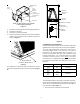
A knockout is provided on the air handler top panel or side
to allow for the entry of the supply voltage conductors. If the
knockouts on the cabinet sides are used for electrical
conduit, an adapter ring must be used in order to meet
UL1995 safety requirements. An NEC or CEC approved
strain relief is to be used at this entry point. The wire is to
be sized in accordance with the “Electrical Wire and MOP”
section of this manual. Some areas require the supply wire
to be enclosed in conduit. Consult your local codes.
Air Handler Only (Non-Heat Kit Models)
The building supply connects to the stripped black and white
wires contained in the air handler electrical compartment
cavity. A ground screw is also contained in this area. Attach
the supply wires to the air handler conductors as shown in
the unit wiring diagram using appropriately sized solderless
connectors or other NEC or CEC approved means.
Air Handler With Non-Circuit Breaker Heat Kits
A terminal block is provided with the HKR kit to attach the
supply and air handler connections. Follow the HKR
Installation Manual and wiring diagram for complete wiring
details.
Air Handler With Heat Kits Containing a Circuit Breaker.
HKR models with a “C” suffix contain a circuit breaker(s).
The air handler has a plastic cover on the access panel that
will require either one or both sections to be removed to
allow the heat kit circuit breaker(s) to be installed. See the
HKR Installation Instructions for further details. The air handler
wires and supply wires are installed directly onto the HKR
circuit breaker(s) as shown in the HKR Installation Manual
and wiring diagram.
Low Voltage Connections
Several combinations of low voltage schemes are available,
depending on the presence of a heat kit and whether the
heat kit is single-stage or multi-staging. The low voltage
connections are determined by whether the outdoor unit is
a condenser or heat pump. The 24V-control voltage
connects the air handler to the room thermostat and
condenser. Low voltage wiring is to be copper conductors.
A minimum of 18AWG must be used for installations up to
50’ and 16AWG for installations over 50’. Low voltage
wiring can be connected through the top of the cabinet or
either side. See the “Thermostat Wiring” section of this
manual for the ARUF, ARPF and ARPT models for typical
low voltage wiring connections. The Supplemental
Installation Manual included with the AEPF product shows
the wiring diagrams for these models.
REFRIGERANT LINES
WARNING
TO PROTECT THE UNIT WHEN WELDING CLOSE TO
THE PAINTED SURFACES, THE USE OF A QUENCHING
CLOTH IS STRONGLY ADVISED TO PREVENT
SCORCHING OR MARRING OF THE EQUIPMENT FINISH.
SOLDER WITH A MINIMUM OF 5% SILVER IS
RECOMMENDED.
Tubing Preparation
All cut ends are to be round, burr free, and clean. Failure to
follow this practice increases the chances for refrigerant
leaks. The suction line is spun closed and requires pipe
cutters to remove the closed end.
Post Brazing
Quench all welded joints with water or a wet rag.
Piping Size
For the correct tubing size, follow the specification for the
condenser/heat pump.
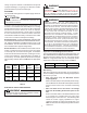
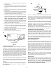
WARNING
THIS COIL IS SHIPPED UNDER PRESSURE. FOLLOW
THESE INSTRUCTIONS TO PREVENT INJURY (SEE
FIGURES 1 AND 2).
Evaporator Coil Metering Devices
Flowrater Models
For most installations no change to the flowrater orifice is
required. In mix-matched applications (condenser/heat
pump is a different tonnage than the air handler), a different
flowrater orifice may be required. See the Goodman piston
kit chart if necessary. Consult your local distributor for the
details regarding mix-matched orifice sizing.