
Install Instructions


9
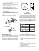
Return Air Side
of Unit
Rear
Channel
Bracket
Zee Coil
Support Bracket
A
ccess
Panel
Coil Retaining
Bracket
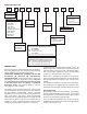
NOTE: The filter provision is not applicable
in THIS downflow application.
Tie Bracket
Figure 4
7. Install the zee coil supports and the wrapper stiffeners.
8. Install the tie bracket.
9. Install the rear channel bracket.
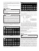
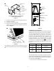
10. To prevent possible condensate “blow off” the insulation
retainers are to be laid into the evaporator coil pan as
shown in Figure 5.
3" Flat Insulation
Retainer (Both Sides)
Figure 5
To complete the conversion, slide the evaporator coil into
the chassis and attach the three (3) access panels. (Figure
6).
WRAPPER
INSULATION
JACKET
ZEE COIL
SUPPORT
WRAPPER STIFFENER
DRAIN PAN
INSULATION KIT
BLOWER
ASSEMBLY
Figure 6
CONVERSION TO HORIZONTAL
Dedicated Downflow models are not suitable for horizontal
application and must not be used for this type of installation.
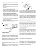
The only field modification required for conversion to
“Horizontal Right-Hand” is the removal of the plastic
knockouts in the horizontal panel drain connections. To
prevent the horizontal drain pan from sweating in high
humidity applications, it is recommeneded that a DPIH
insulation accessory kit be used. NOTE: The DPIH
insulation kit is not supplied with this product and should
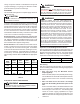
be purchased seaparately. See Table 8A for the correct
DPIH kit.
ARUF / ARPF AEPF INSULATION KIT
1729
1824
3030
1931
3642 3036
3743 DPIH48-61
4860 4260
1830 DPIH36-42
N/A DPIH18-32
Table 8A
The following describes converting to “Horizontal Left-Hand”.
Conversion to downflow MUST be performed in an area that
allows access to all sides prior to placing the air handler in
its final location (See Figure 7).
1. Remove the (3) air handler access panels.